
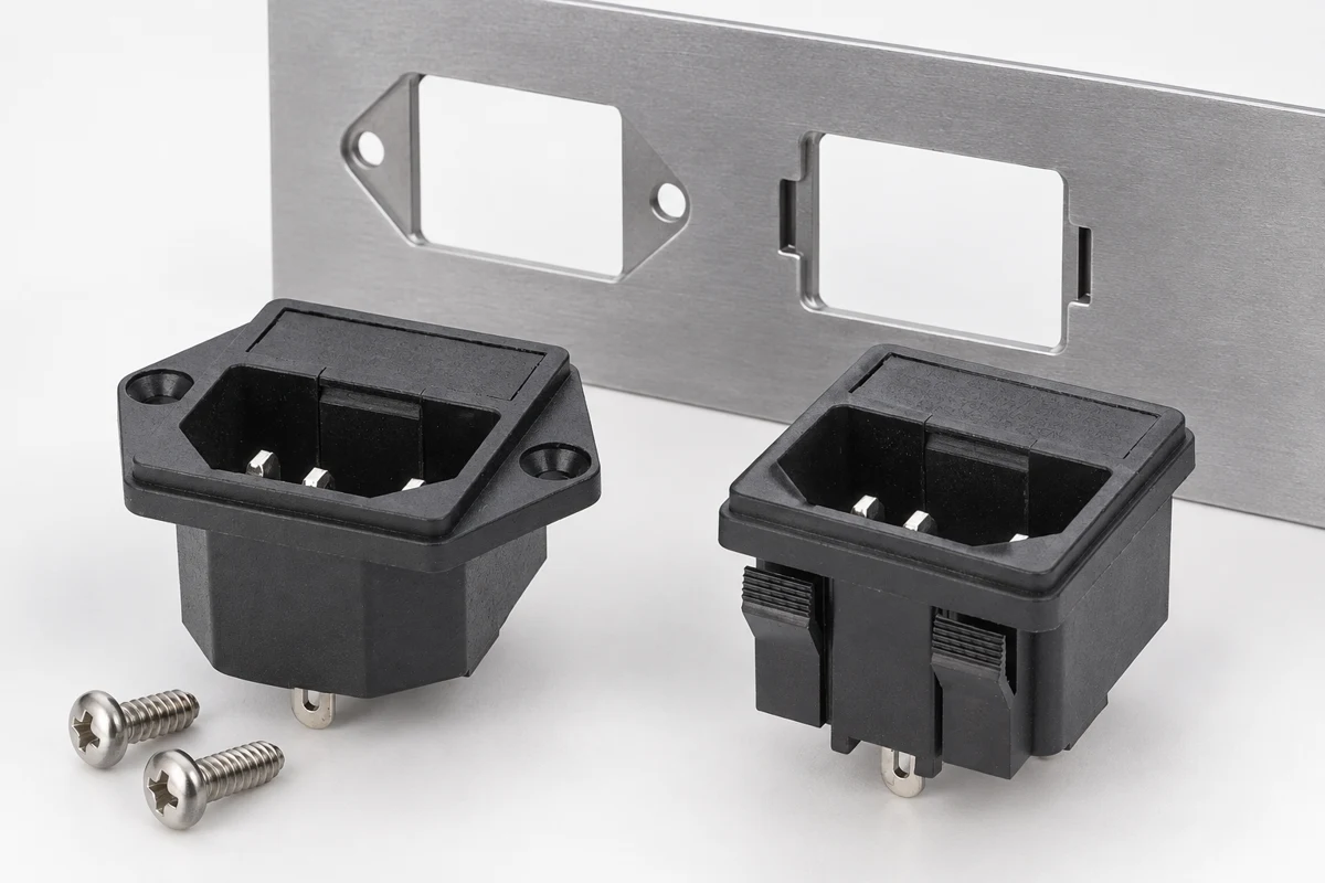
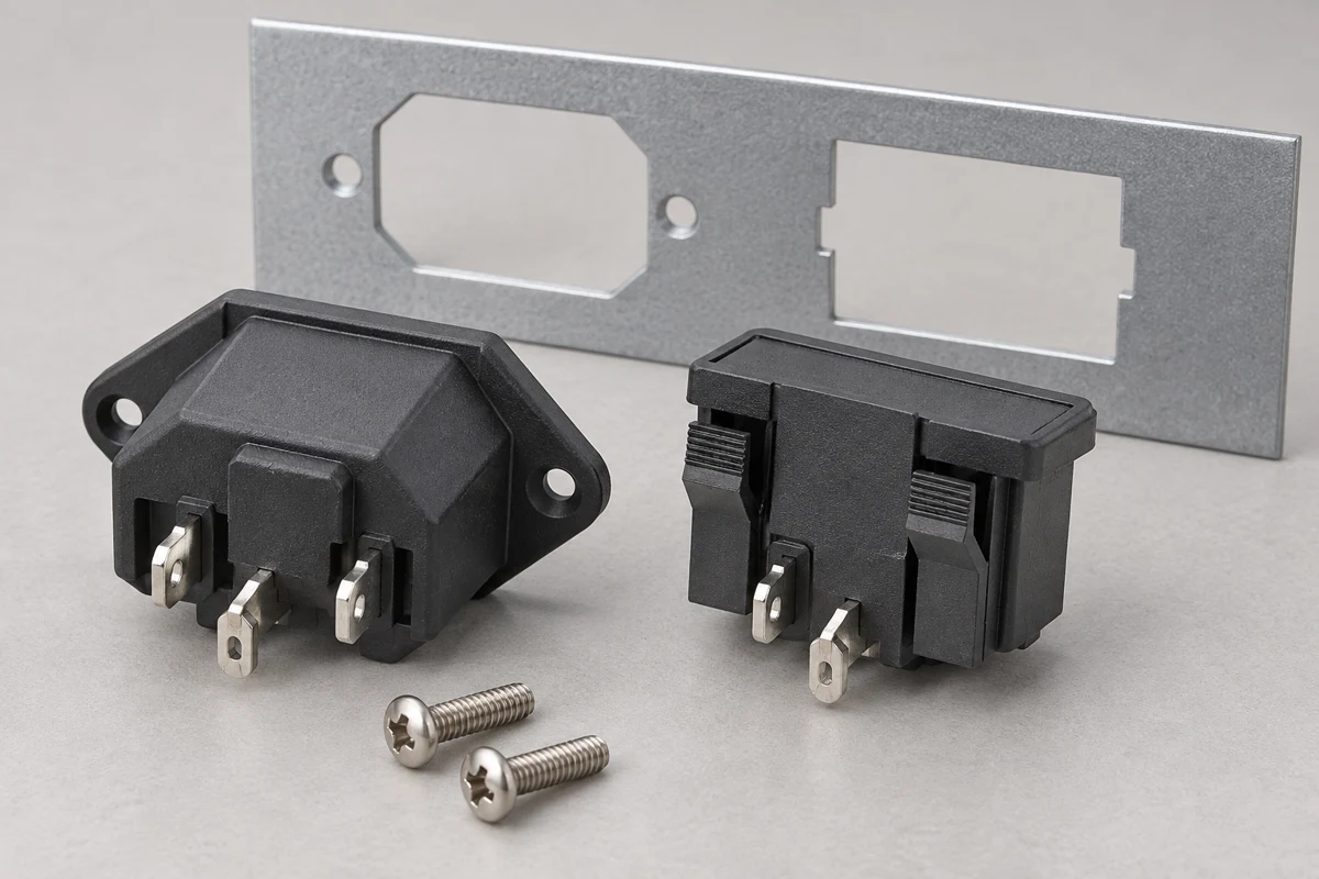
Snap-in versus screw-mount power inlet selection starts with the enclosure, not the connector name. A snap-in inlet relies on its specified retaining features engaging a panel within an approved thickness and cutout range. A screw-mount inlet uses a flange and compatible fasteners to secure the body. Either approach can work when the actual inlet drawing, finished panel, wiring space and service method agree. Neither approach is automatically stronger, more waterproof or electrically safer merely because of its mounting style.
This guide concerns equipment appliance inlets, such as the LEMA IPZ product family. It does not compare household receptacle push-in wire connections. Keep mechanical retention separate from the terminal connection method: a snap-in body can still use solder or quick-connect terminals, and a screw-mounted body can use several terminal arrangements.
Compare retention paths rather than marketing labels
Sketch the path followed by a force when a user inserts or removes the mating cord connector. It travels through the inlet body, retaining clips or flange, and finally the enclosure panel. A retention problem anywhere in that path can allow movement even if the electrical connection remains continuous. Evaluate pull, push and sideways loading separately; a housing that resists straight extraction may still rock in an oversized hole.
For snap-in mounting, identify which surfaces grip the rear of the panel and which stop against the front. For screw mounting, identify the flange bearing surface, screw engagement and any backing feature. Record these details on the assembly drawing so the shop can inspect the real load path, instead of judging the installation by how firmly the part seems to click.
Panel thickness includes coatings and local features
The usable panel thickness is the finished thickness at the mounting interface. Paint, powder coating, laminates and a raised reinforcing feature can change the dimension that the retaining clip sees. A catalog statement about nominal sheet thickness is not enough if production parts have varying coatings or an edge that curls during punching. Measure finished examples where the inlet actually seats.
Ask the inlet supplier for the permitted panel thickness interval and the relationship between that interval and the cutout. Do not infer this from another part with a similar front face. A snap feature that cannot fully recover behind a thick panel may leave the flange standing proud. A very thin panel can leave free movement. Screws avoid that particular clip engagement problem, but still require suitable thread engagement and flange support.
Use the correct cutout revision
IEC connector compatibility concerns the mating interface; it does not make every manufacturer’s mounting flange interchangeable. The IEC appliance coupler dimensional standard provides the connector framework, while the chosen supplier drawing controls the equipment cutout. Obtain the complete order code and drawing revision before releasing tooling. Dimensions copied from a marketplace photograph are unsuitable for production.
Define width, height, corner radii, locating features, thickness and surface condition together. A correct overall rectangle can still reject a housing if the corner radii are incompatible. Likewise, enlarging a hole to make insertion easier can remove the overlap required for retention. Use an inspection coupon before machining an entire batch, and retain the approved coupon or gauge as a shop reference.
Choose around assembly and service access
A snap-in body can reduce fastening steps, but only if the operator can insert it squarely and verify full engagement. Plan a visible or measurable engagement check. If the enclosure prevents inspection of the rear clips, establish another validated method rather than assuming that one audible click means every retaining feature is seated.
A screw flange introduces fastener handling and a controlled tightening step. In exchange, it may suit an enclosure where service staff need a predictable removal method. Confirm that the tool reaches the fasteners after surrounding components are installed. Consider both initial assembly and field replacement: the lowest assembly time is not necessarily the lowest lifetime maintenance cost.
| Decisión | Snap-in check | Screw-mount check |
|---|---|---|
| Ajuste de paneles | Approved thickness and full clip engagement | Flange contact and compatible fastener support |
| Production control | Cutout and coating repeatability | Fastener type, access and specified tightening method |
| Servicio | Permitted release method and clip condition | Removal access and reusable mounting arrangement |
| Cord loading | Body does not rock during handling | Flange and panel carry handling load |
| Sellado | Exact tested gasket or seal arrangement | Exact tested flange and fastener arrangement |
Keep cord forces away from terminals
Mechanical retention and conductor strain relief have different jobs. The enclosure mount carries the inlet body. Harness support prevents wires from transferring their bending or tensile force into the rear terminals. A firm flange cannot compensate for an unsupported harness, and a tied harness cannot correct a loose inlet body.
Route the internal wires with adequate access for the approved termination process. Check that closing the enclosure does not push a connector sideways or fold a wire against a sharp edge. NASA’s wiring workmanship standard is useful background for controlled harness construction, but apply the requirements selected for the equipment and the component maker’s instructions. Do not represent a general workmanship reference as a certification of the inlet.
Check movement under realistic connector handling
Build a disconnected prototype using the production panel finish and intended mating connector. Observe flange movement during insertion and removal. Test the directions expected during installation and service. Have the design authority define the acceptance loads and method; there is no universal hand-pull test that qualifies all equipment.
Also check what happens when a stiff cord approaches from an angle or an installer supports the machine by the enclosure nearby. The inlet must not become a lifting point. Record whether the panel flexes, the clip moves, or the body rocks. This distinguishes a panel stiffness issue from a retaining feature mismatch. Altering the housing or filing the clip to fit is a design change, not routine assembly adjustment.
Account for polymer behavior and repeated removal
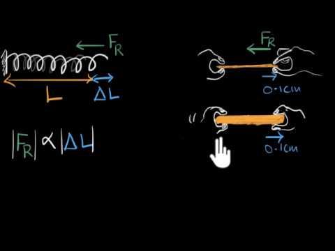
A snap feature depends on a shaped part deflecting during insertion and returning sufficiently to retain the housing. Its behavior depends on geometry, material and environment. The accompanying Khan Academy lesson introduces stress and strain, helping explain why a deflected part may not recover after it has been pushed beyond its intended range. It does not establish the limits of any particular inlet.
Ask whether repeated removal is permitted and which tool or procedure is required. Never assume a clip can be bent back indefinitely. If the expected service process involves frequent disassembly, compare the approved removal procedure with a fastener-based alternative. In either case, inspect the body for cracking and the panel for damage before reusing a removed component.
Resolve gaps without inventing a seal
An inlet that sits flush is not necessarily sealed. If the panel is exposed to dust or liquids, identify the complete sealing arrangement and any specified gasket. The screw holes, mating face and rear wiring can present different entry paths. Mounting style alone does not establish an IP classification.
Do not use improvised foam, adhesive or extra washers merely to remove visible movement. Such additions can prevent clip engagement, change flange compression or interfere with connector mating. If a gap remains, first compare the finished panel to the approved drawing and the actual body to the ordered variant. Request a supplier-approved solution and validate it on the intended assembly.
Prepare a purchasing and acceptance record
A useful request for quotation includes the full inlet order code, mating connector family, finished panel material and thickness range, cutout drawing revision, mounting approach, terminal option, internal clearance and expected service method. Supply photographs of the relevant panel region and a sample coupon when the geometry is unusual. Request written confirmation of any retention and sealing claims that matter to the design.
For incoming inspection, distinguish the physical mount from electrical identity. Check the clip or flange version, terminal form and any keying feature before it reaches assembly. At assembly, record seating, retention and harness clearance. After any supplier or panel tooling change, repeat the checks that depend on that change. Contact LEMA with the assembly record to discuss an IPZ option; do not release a substitute based only on a matching front photograph.
Further learning
This neutral physics lesson explains material deformation. It supports the discussion of clip deflection and recovery; use the inlet drawing and assembly tests for actual retention acceptance.
Recursos relacionados de LEMA
- Snap-In vs Screw-Mount IEC Power Inlet product reference
- Equipment power inlet selection
- Panel cutout drawing checks
- Integrated module versus separate components
Technical references
- IEC appliance coupler dimensions: Defines appliance coupler standard sheets; request the exact supplier mounting drawing for the enclosure cutout.
- NASA wiring workmanship standard: A reference for controlled cable and harness workmanship; it does not certify the illustrated LEMA part.
Preguntas frecuentes
Is snap-in mounting the same as push-in wiring?
No. Snap-in describes how the housing is retained in the panel. Push-in wiring describes a conductor termination. Specify the housing mount and rear terminal method independently, and avoid transferring advice about household outlet wiring to an equipment inlet.
Can a screw-mounted inlet use the same cutout as a snap-in version?
Only if the exact drawings confirm it. Similar mating faces do not establish identical body envelopes, flange overlap, hole positions or corner radii. Compare the ordered parts and approve the enclosure drawing before substitution.
Does adding screws improve every snap-in installation?
No. Drilling or modifying a snap-in housing can damage the part and change its evaluated construction. If retention is inadequate, correct the drawing mismatch or select an approved flange variant rather than inventing a fastening method.
What should a buyer send before ordering samples?
Send the inlet and mating connector identities, panel drawing, finished thickness range, terminal requirements and service constraints. State which retention and environmental checks the sample must pass. Ask for the supplier drawing rather than requesting a generic snap-in replacement.