
Match the replacement to the machine, not just the switch body
A micro switch replacement must match the original contact function, mounting geometry, actuator movement, terminal arrangement and electrical duty. A switch that fits the screw holes can still change the operating point, reverse a control signal or fail prematurely under the connected load. Start with the equipment service instructions and the complete original part number, then compare the proposed replacement against a current drawing and rating sheet. For industrial and appliance assemblies, treat an undocumented substitution as an engineering change requiring validation. This guide explains how to build that comparison without assuming that similar-looking switches are interchangeable.
The scope here is a mechanically actuated snap-action component, such as the models in the LEMA micro switch range. It does not provide an approval to replace a machine safety device, a sealed appliance assembly or a manufacturer’s proprietary service part. Those cases may require an exact approved component or a complete assembly. Do not bypass an interlock to keep equipment running while a replacement is being sourced.
Record the original installation before removing anything
Identify the equipment, assembly revision and original switch order code. Photograph the switch from the actuator, mounting and terminal sides, with the circuit isolated. Record the markings exactly, including voltage, current, temperature codes and any separate load-specific ratings. A supplier logo or a partial family name is not enough: terminals, actuators and contact materials can vary within one product family.
Record how the actuator contacts the moving mechanism. Note whether a cam touches a roller, a bracket presses a plunger, or a door deflects a lever. Include the normal rest position and the position at which the equipment expects the contact to change. If the machine service procedure provides an adjustment or test fixture, use that procedure as the reference. Do not infer the original operating point from a bent or worn lever.
Label conductors using the circuit designation and terminal identification before disconnecting them. Wire color alone is an unreliable substitute for a diagram. Save the original fasteners, washers and mounting orientation as evidence, but inspect their condition before reuse. A stripped mounting hole or cracked bracket can make a correct replacement perform poorly.
Isolate energy and confirm the fault
A component should not be replaced solely because the machine does not start. The fault may be in a connector, damaged cable, actuator alignment or control input. Follow the site’s isolation procedure and the machine instructions before inspection. Electrical, pneumatic, hydraulic, gravitational and stored mechanical energy can all matter. The Guía de OSHA sobre el control de energía peligrosa explains why maintenance requires effective control of unexpected energization and stored energy.
Continuity checks belong on an isolated contact circuit with parallel paths accounted for. They can establish whether a contact changes state consistently, but they do not prove load capacity, insulation performance or service life. See the complementary micro switch multimeter testing guide for the diagnostic boundary. Stop if the component is part of a safety function whose test requirements are not known.
Look for mechanical causes as well as electrical symptoms. Loose mounting, excessive travel, a damaged roller or side loading can recreate the fault immediately after replacement. If a failed terminal shows heating, inspect the mating connection and conductor termination. Replacing only the switch does not repair a loose connector or an incorrectly specified load.
Compare contact function and terminal identification
Determine whether the original device is normally open, normally closed or changeover, and what those states mean at the unactuated position. On a changeover device, common, normally open and normally closed are functional designations; their physical positions must come from the exact drawing. Never assume that three terminals follow a universal left-to-right arrangement.
Write a simple state table for the application: actuator released, actuator at its intended operating position, and actuator returned. Compare the original circuit expectation with the replacement contact arrangement. The important result is the signal observed by the equipment in each state, including any controller logic that inverts the input. A contact that is closed at rest may be required for fault detection even when the visible process action seems to suggest otherwise.
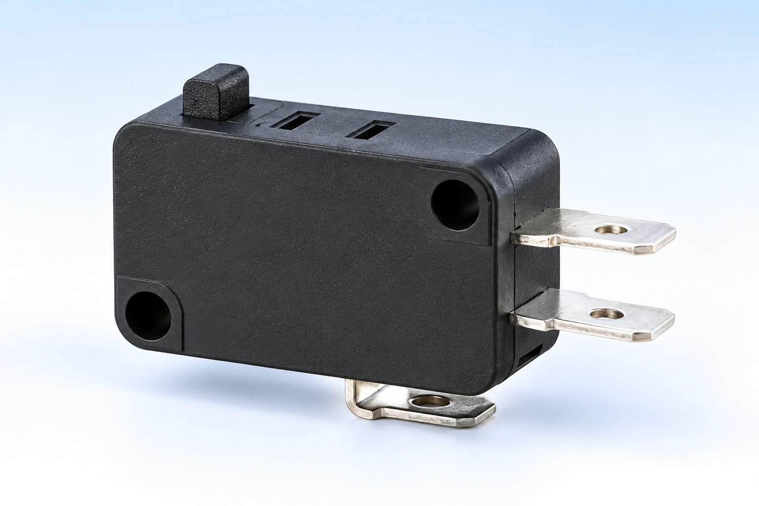
Utiliza el guía de selección de microinterruptores industriales as the broader specification reference. This replacement comparison is narrower: every accepted difference must have a documented reason and a validation step. Do not convert an originally normally closed monitoring circuit to normally open merely because a convenient replacement is available.
Check form, fit and travel as separate requirements
Compare body dimensions, mounting hole centers, fastener size, clearance around the terminals and the available envelope for actuator movement. Confirm the orientation used in each drawing before comparing measurements. Two drawings may show opposite sides of the switch, making an apparently mirrored terminal arrangement easy to overlook.
Then compare actuator geometry. Lever length, roller diameter, pivot position and plunger height influence where the mechanism first operates the contact. A longer lever may change the force and travel requirements even when it fits the enclosure. The machine’s available stroke must operate the switch reliably without using the switch body as a mechanical stop.
Operating position, pretravel, overtravel and differential travel describe different points in the movement. Use the exact manufacturer’s values and tolerances; there is no universal adjustment distance. The guide to micro switch travel terms explains those differences. Validate both the outgoing motion and return motion, because a replacement that operates correctly may still release at the wrong point.
| Comparison | Pruebas a recopilar | Reason to hold the substitution |
|---|---|---|
| Contact function | Original circuit and replacement contact diagram | Required released or operated state differs |
| Montaje | Dimensioned drawings and bracket inspection | Holes align only when the body is forced or modified |
| Actuator travel | Operating and release positions, tolerances and machine stroke | Insufficient margin or excessive overtravel |
| Servicio eléctrico | Voltage, AC/DC, load category and relevant ratings | Only a headline current value matches |
| Termination | Terminal dimensions, connector and conductor specification | Loose mating fit or unsupported soldering process |
| Medio ambiente | Local temperature, contamination and required sealing | Rating applies to a different installation boundary |
This table is a qualitative substitution checklist, not a set of invented tolerances. Acceptance limits must come from the equipment documentation and the exact proposed component.
Match electrical duty and the termination system
Compare the actual circuit voltage and whether it is AC or DC. Identify whether the switch handles a controller input, a relay coil, a lamp or another load. A resistive current rating does not automatically establish suitability for an inductive load. A part that handles substantial current may also require confirmation for a very low signal current. Preserve the intended contact material and load conditions rather than selecting only the largest current number.
Check terminal style, blade width and thickness, solder requirements or PCB footprint as applicable. A connector that can be pushed onto a blade is not necessarily the correct mating component. Inspect retention and strain relief, and follow the specified assembly method. Do not file terminals, bend them into a different footprint or use solder as a substitute for a proper mechanical connection.
If the original failed with arcing or welding, investigate the load and suppression arrangement before commissioning a new part. A continuity meter cannot establish that those conditions are corrected. The equipment designer must decide whether the switch should control a relay or contactor instead of carrying the load directly. Do not introduce a new interface without reviewing its effect on the control function.
Confirm the environment and the exact product evidence
Measure the environment at the installed switch, not only the room. Nearby heaters, motors, contamination and cleaning processes may create more demanding conditions. Confirm whether a seal rating describes the complete switch, an actuator boundary or an assembled installation. A terminal connection outside the sealed region may still need protection.
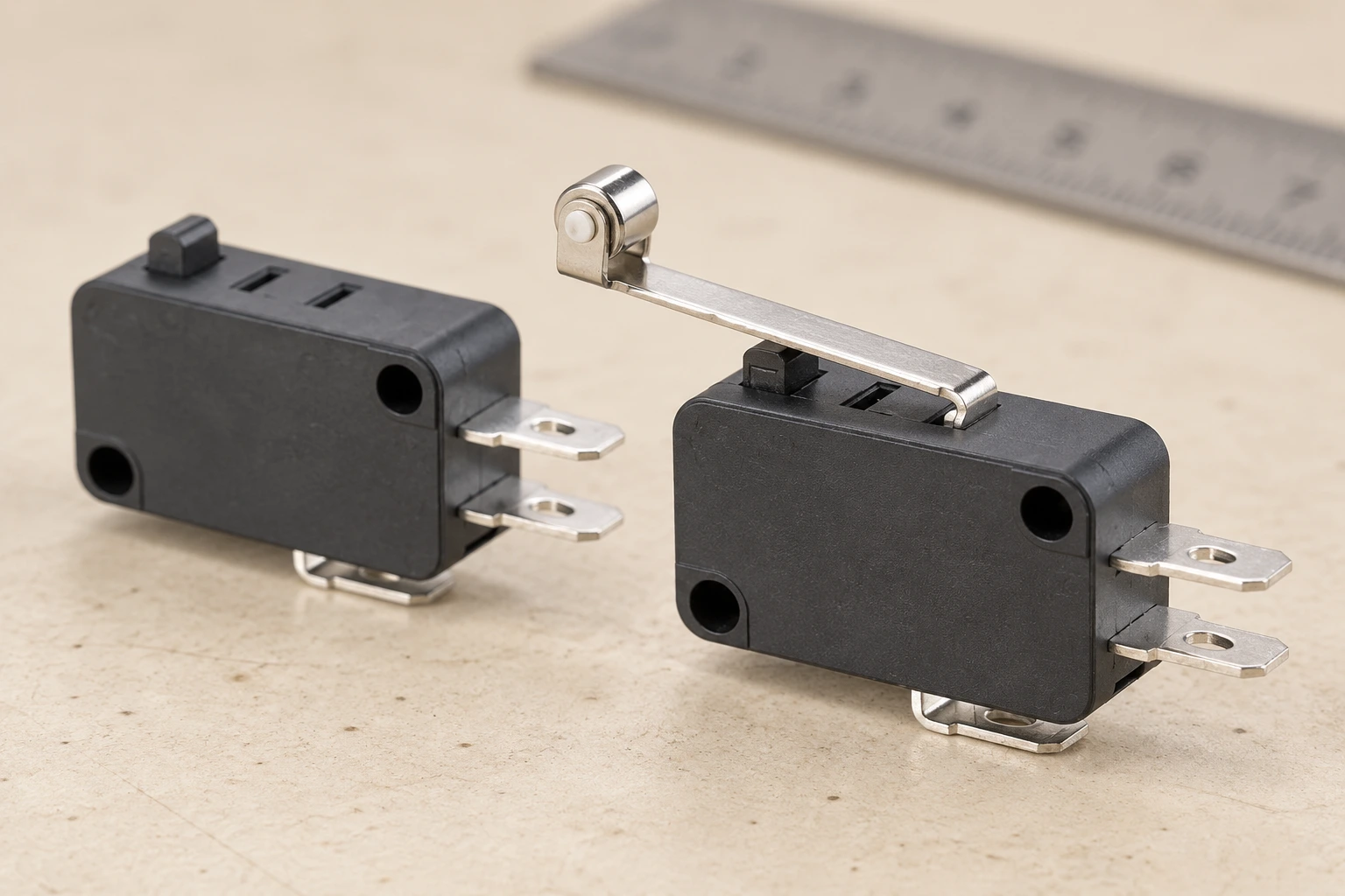
The product illustrations here use real LEMA KW7 references to show body, lever and terminal features. They are not proof that a particular order code replaces another brand, that every KW7 variant has the same ratings, or that a model is suitable for a safety function. Request the current drawing and specification for the selected variant. Include the original switch photographs and installation measurements when asking LEMA to review an OEM replacement requirement.
Validate the replacement before returning equipment to service
Perform the specified isolated contact checks, then inspect mounting security and clearance across the complete mechanism movement. Confirm that the mechanism operates and releases the contact at the required positions without impact, binding or excess force. Record the results against the machine’s acceptance limits. A single successful actuation is not enough to demonstrate consistent alignment.
Return the equipment to service only under its authorized commissioning procedure. Check the actual control signal, expected response and any required restart behavior. The HSE machinery maintenance guidance emphasizes planned maintenance and competent work. Where protective functions are involved, the required verification must be completed by people qualified for that system.
For background on the contact principle, the RealPars educational video below explains mechanically actuated position switches. It supports understanding of actuation and contact changes; it is not a replacement approval or a service procedure for the equipment.
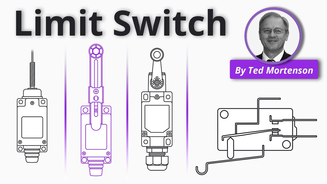
Watch the RealPars explanation on YouTube.
Keep an approved replacement record
Record the original and replacement order codes, drawing revisions, accepted differences, installation settings and test results. Keep the component traceability information with the machine maintenance record. For a production change, update the bill of materials and assembly instructions so later technicians do not have to repeat an undocumented substitution.
Send a complete inquiry through LEMA’s contact page: include annual quantity, exact function, mechanical drawing, load conditions, environment and approval requirements. A clear comparison package is more useful than asking for a visually identical switch. If a critical requirement cannot be confirmed, retain the original approved specification and hold the substitution.
Preguntas frecuentes
Can I replace a micro switch with a higher-current model?
Only after checking all relevant requirements. Higher headline current does not establish matching contact material, low-current behavior, load category, travel, termination or approval. Compare the exact duty and complete installation.
Are three-terminal micro switches interchangeable?
No. Three terminals often indicate changeover contacts, but terminal positions, dimensions, actuator geometry and ratings can differ. Use the exact contact diagram and a documented mechanical comparison.
Should I bend the replacement lever to make it fit?
Do not improvise a lever modification. It can change operating force, travel and fatigue behavior. Use an approved actuator option or a documented equipment-specific procedure.
Does a successful continuity test prove the replacement is safe?
No. It verifies contact state under the test conditions. It does not prove insulation, load endurance, environmental performance, protective-function suitability or correct machine response.