
Micro switch minimum load describes the lower switching conditions supported by a particular contact system under stated test conditions. A maximum current rating does not establish reliable operation at a tiny signal level. Validate the actual input circuit, contact variant, environment and required reliability rather than assuming that every power-rated switch is suitable for a dry circuit.
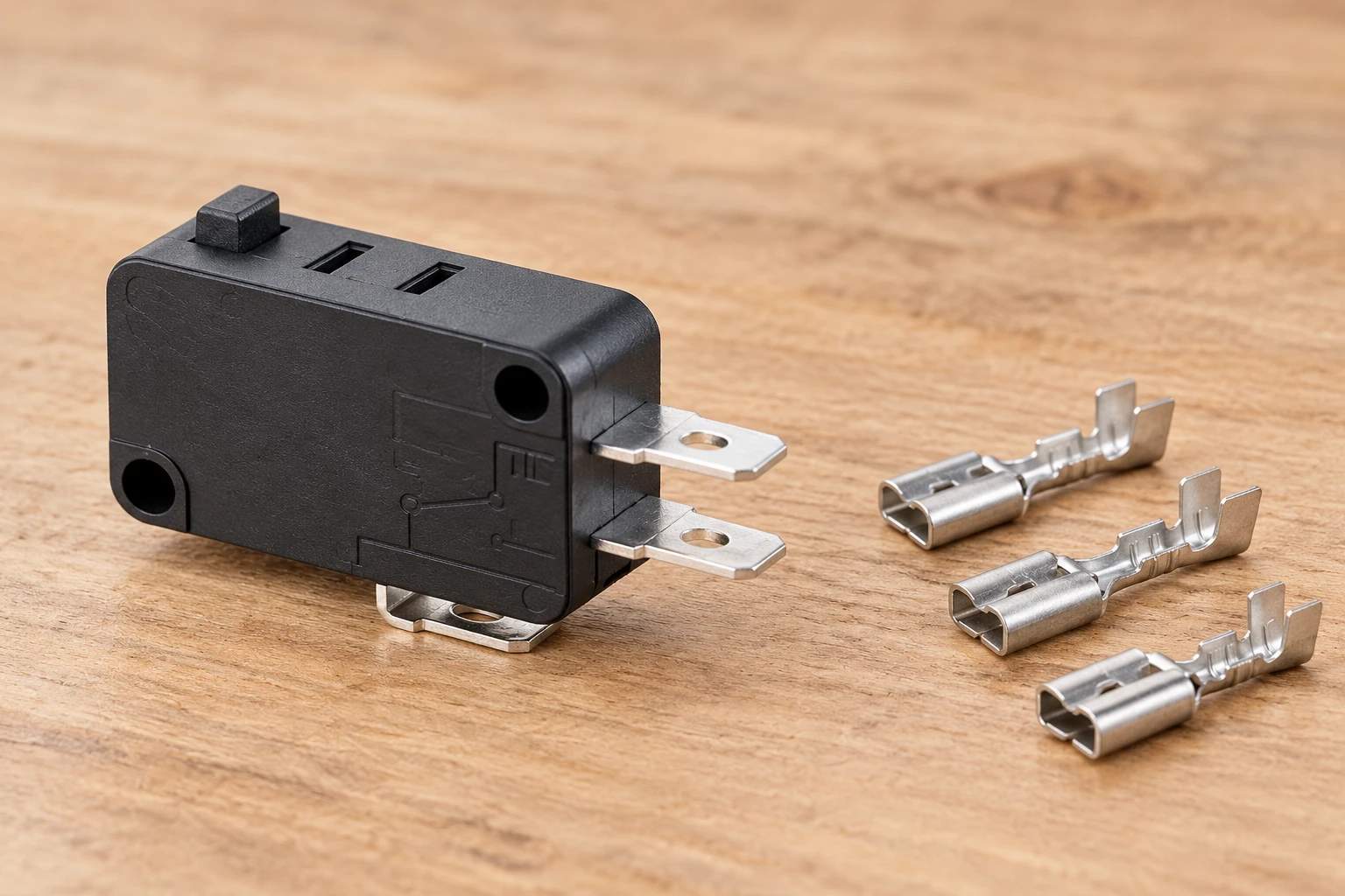
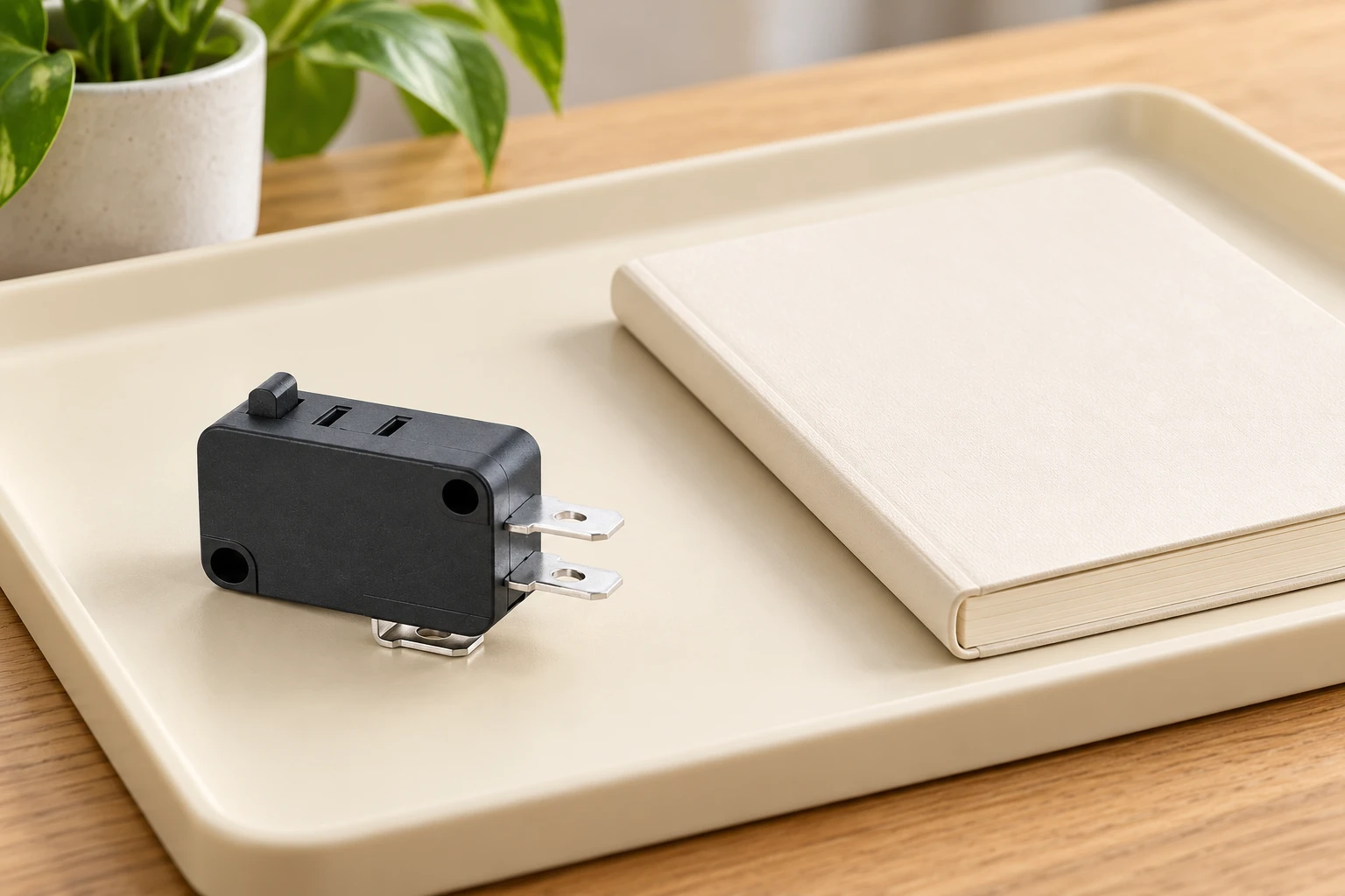
El Microinterruptor de la serie KW7 is the LEMA product reference illustrated here. Its photograph identifies the external product, not an unlisted rating, accessory compatibility or test result. Obtain the current specification for the full order code before approving an assembly.
Why an Upper Rating Does Not Establish a Minimum Load
An upper electrical rating describes an allowable switching duty under stated conditions. It does not automatically identify the lowest voltage or current at which the contact will function reliably. A contact arrangement that performs satisfactorily with an energetic load may depend partly on electrical effects that are absent in an electronic sensing circuit. Reading the upper rating backward creates an unsupported assumption: that anything electrically smaller must be easier.
At low signal levels, contact resistance can become unstable because the conducting interface is influenced by films, surface condition, contact force, and microscopic contact spots. The receiving input may interpret that instability as an open circuit, delayed transition, or intermittent state. Meanwhile, the switch may still operate mechanically and sound normal. Mechanical action alone does not demonstrate electrical suitability for the application.
When documentation gives a minimum applicable load or a low-level designation, examine its scope. Ask which contact construction, environment, operating history, and acceptance method support the statement. A published designation is useful evidence, but it is not permission to substitute different terminal finishes, contact options, sealing arrangements, or operating conditions without reviewing their relevance.
Contact Films and the Meaning of Wetting
Closed contacts do not meet across perfectly clean, uniform surfaces. Current passes through localized contact spots influenced by roughness, force, sliding action, and surface layers. Those layers can include oxides, sulfur-related compounds, adsorbed substances, and contamination introduced during production or service. Their electrical behavior depends on the contact material and surrounding conditions, so apparently similar switches may respond differently.
Wetting describes electrical conditions that help establish or maintain conduction through the contact interface. Depending on the contact system, electrical energy may disturb a resistive film or alter the conducting spots. However, treating wetting as a universal current value is misleading. Voltage, available current, source impedance, waveform, duration, switching sequence, and surface history all influence the result. Contact geometry and mechanical action matter as well.
There is no universal wetting current for micro switches. A current that appears effective on fresh samples may not establish reliable operation after storage or environmental exposure. Conversely, increasing current without considering voltage and available energy may fail to address the actual mechanism. If a design relies on intentional wetting, validate the complete electrical event and its consequences for contact life, input protection, and system behavior.
Define the Actual Input Before Choosing a Test
Begin with the receiving circuit rather than an assumed contact load. Document the input topology, pull-up or pull-down arrangement, supply variation, filtering, protection components, wiring, and grounding. Identify what the controller considers a valid state and how it handles transitions. A switch connected through a harness and protection network may experience conditions unlike those implied by the nominal supply.
Determine the voltage across the open contact and the current through the closed contact. Then examine what happens during closure and opening. Input capacitance, cable capacitance, protection networks, and firmware-controlled sensing can produce transient behavior that a steady-state calculation misses. The contact may receive a brief charging event followed by a much weaker holding condition, or it may encounter different conditions depending on the system state.
Measurement must preserve those conditions. Instrument input resistance, capacitance, grounding, and test leads can change a sensitive circuit. A resistance meter can apply an electrical stimulus unrelated to the application and potentially change the contact surface before the functional observation. Select instruments and connections deliberately, document their influence, and correlate contact measurements with what the controller actually registers.
Compare Duties Without Treating Them as Interchangeable
| Duty or evidence | What it helps establish | What it does not establish alone |
|---|---|---|
| Upper electrical rating | Suitability for a stated load category | Reliable recognition by a sensitive input |
| Low-level contact designation | Supplier intent for signal applications | Compatibility with every sensing circuit |
| Contact material specification | Relevant surface and wear characteristics | Validated performance after application aging |
| Fresh-sample functional test | Initial operation in the test configuration | Resistance to storage and environmental effects |
| Representative dry-circuit validation | Performance under controlled low-energy duty | Suitability after untested load changes |
Build a Dry-Circuit Validation Plan Around the Application
Define dry-circuit conditions explicitly in the qualification plan. The purpose is to evaluate conduction without allowing the test stimulus to clean, break down, or otherwise condition surface films in a way the application would not. Do not assume that a laboratory instrument’s default continuity or resistance mode meets that purpose. Confirm its open-circuit stimulus, available current, transient behavior, and behavior when changing ranges.
Use representative switches, terminals, mounting arrangements, actuator geometry, and wiring. Actuation position, overtravel, release behavior, and mounting stress can affect contact engagement. A fixture that drives the switch differently from the product may obscure a marginal design. Include relevant variations in assembly and operation, especially where housing tolerances or actuator alignment influence the final contact state.
Establish acceptance criteria before testing. These should address recognized input states, transition behavior, intermittent events, and recovery, not merely whether the contact eventually conducts. Relate any resistance criterion to the real input’s operating margin. Define how events are captured and reviewed, including failures that disappear after another operation. Retain individual sample histories so that a temporary anomaly is not lost inside an overall pass result.
Include Aged Samples and Realistic Exposure
Fresh contacts can give an optimistic picture of low-level performance. Storage and service expose surfaces to conditions that may change films, contamination, lubrication, and mechanical behavior. Qualification should therefore include samples aged in ways relevant to the product’s expected environment. Consider packaging, warehouse conditions, assembly processes, enclosure materials, humidity, temperature variation, and nearby substances that could reach the contact system.
Distinguish environmental exposure from mechanical endurance and electrical endurance. Repeated operation can move surface material or alter contact spots, while storage can leave an undisturbed interface. These histories are not interchangeable. Where relevant, evaluate both contacts left idle and contacts operated during exposure. Keep the sequence representative of how the finished product will actually be manufactured, stored, commissioned, and used.
Pay particular attention to the first operation after an idle period. A contact that becomes dependable after repeated actuation may still be unsuitable for an alarm, interlock, or infrequently used command. Record initial behavior before exercising the switch further. If installation or commissioning includes an intentional conditioning step, validate it as a controlled process rather than assuming service personnel will provide it accidentally.
Keep High-Current Testing Out of the Low-Level Sample History
One of the most consequential validation errors is exposing a low-level sample to a stronger electrical load before evaluating its dry-circuit behavior. That exposure can modify films, create localized heating, transfer material, or change the contact surface. A later successful low-level test may then describe a conditioned contact rather than the contact the customer will receive.
This contamination of test history can happen unintentionally. Incoming inspection, troubleshooting, continuity checks, production fixtures, and shared endurance rigs may all apply inappropriate electrical stress. Even a brief diagnostic step can make the sample unsuitable for answering the original qualification question. Separate sample groups by intended duty and record every electrical exposure, including measurements made outside the formal test sequence.
If the product genuinely alternates between power duty and signal duty, test that mixed history deliberately. Do not infer suitability from separate power and signal evaluations. Contact wear or surface transfer produced by the energetic load may change later low-level performance. Conversely, a successful mixed-duty result supports only the tested sequence and conditions, not unrestricted interchangeability between duties.
Preserve low-level evidence through the test sequence
Characterize the actual control input, including its source voltage, available current and any input conditioning relevant to the contact. A static multimeter measurement does not reproduce every sensing circuit. Record the sample history and the observation method. Testing a contact at a substantially different duty before a low-level assessment can change the surface condition and make the sequence unrepresentative.
Use fresh or appropriately conditioned samples as required by the approved plan and document their history. Never add an arbitrary wetting current to a controller input without an engineering assessment of that circuit and the component. The illustrated KW7 product identifies a family to discuss, not a verified dry-circuit option. Ask LEMA which exact contact variant and evidence apply to the intended signal and environment before approving it.
Technical references and the scope of this review
El IEEE overview of electrical contacts distinguishes constriction resistance and film resistance associated with surface layers or contaminants. This provides physical background; it is not a minimum-load qualification for the illustrated LEMA variant.
IEC 61058-1 scope for appliance switches: Use the applicable contact specification for the exact variant. A general maximum rating or standard title does not establish a minimum switching capability.
HSE guidance for electrical testing: Even a low-level test must account for any connected equipment and stored energy. Define an isolated test boundary and an approved method before investigating a control input.
For the wider component decision, see Selección de un microinterruptor industrial para paneles OEM. Complementary checks are covered in Elegimiento entre contactos de microinterruptores de oro y plata y Resistencia de contacto del microinterruptor: causas, pruebas y límites. These pages address separate questions and do not replace the acceptance evidence defined here.
Further learning
This independent workshop video explains micro switch operation. It provides mechanism background, not evidence that the illustrated contact variant supports a particular minimum load.
Watch All about Micro-switches! — Vinny’s Workshop
Preguntas frecuentes
Does a large maximum rating prove low-level reliability?
No. The supported minimum conditions and actual signal duty require separate evidence.
Can I add a wetting current to any control input?
No. Assess the complete circuit and component before making such a change.
Can an earlier power-load test affect low-level evidence?
It can change contact surface conditions. Define the sequence and sample history in the approved method.
Is KW7 automatically a dry-circuit switch?
No such blanket claim is made. Confirm the exact contact variant and applicable evidence with the supplier.