
Micro switch parallel contacts should not be used to add current ratings unless the manufacturer explicitly supports the arrangement and its conditions. Two contacts do not necessarily close together, share current equally or open together. The first contact to close and the last to open may face a different duty from the steady parallel combination. For an OEM build, define the purpose of paralleling, examine each credible contact state and select a supported switching arrangement instead of treating two catalog ampere values as arithmetic capacity.
Clarify the reason for a parallel path
A proposal to connect contacts in parallel can start with several different problems: insufficient current capacity, a desire to keep a circuit available, or an attempt to reduce resistance. These are separate objectives. Write down the actual requirement before changing the harness. A circuit that remains energized after one contact sticks may satisfy an availability objective while violating the intended stop behavior.
Draw every contact, common terminal and wire connection. Identify whether there are two separate switches, two independent poles in one device, or the NO and NC terminals of an SPDT mechanism. Those arrangements cannot be treated as equivalent. In particular, the two throws of an SPDT switch are alternate destinations; joining them does not create two independently specified simultaneous closed poles.
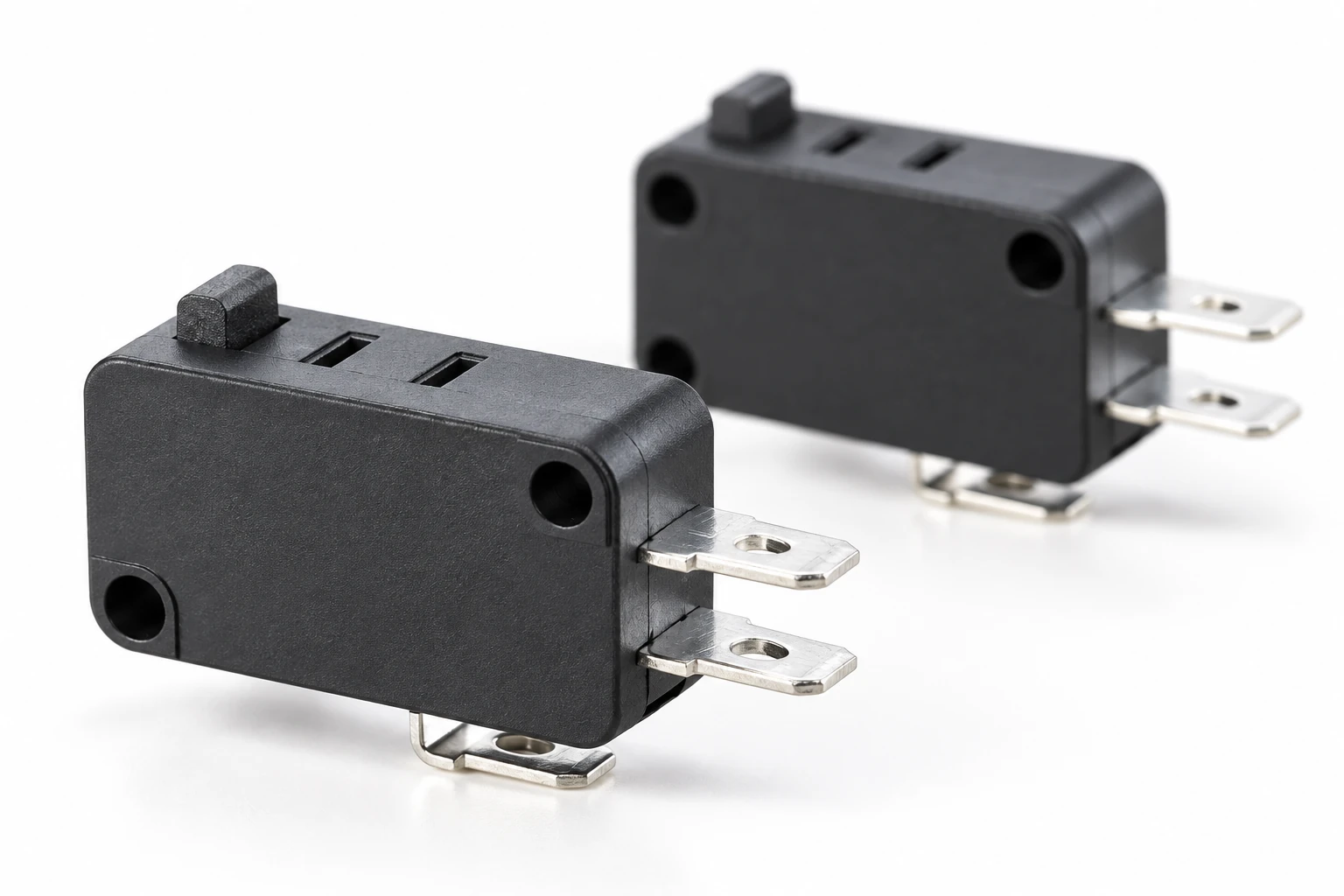
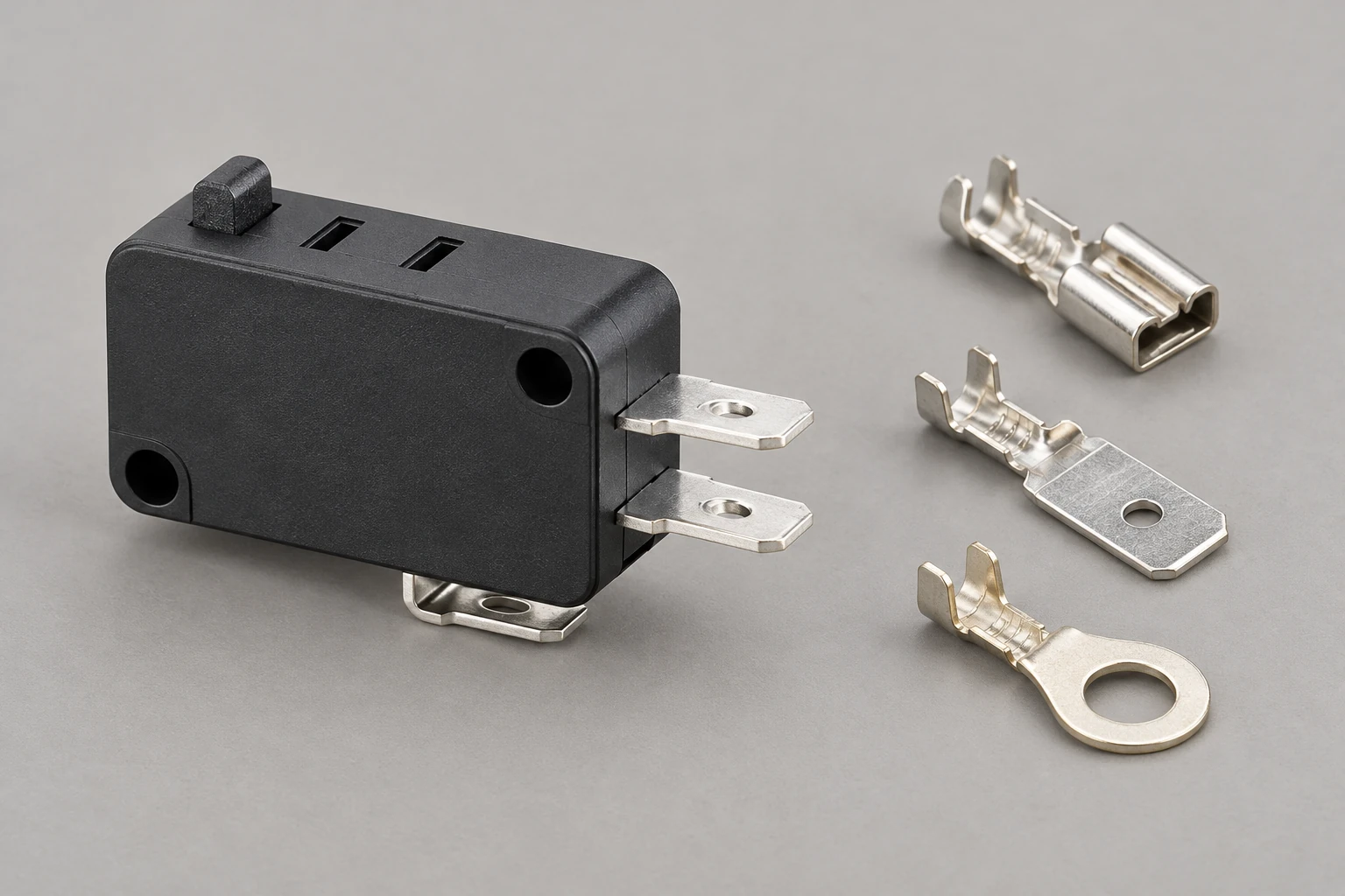
Utiliza el micro switch wiring guide to establish the normal terminal logic before discussing a changed topology. Confirm the actual variant and diagram from the supplier. The KW7 family provides a physical product reference, but its appearance does not establish pole independence, synchronized operation or permission to parallel contacts for a higher load.
Separate the steady circuit from the switching sequence
When two conducting branches share the same pair of nodes, their currents depend on their branch resistances. The MIT explanation of parallel resistors explains that circuit distinction. A branch includes its wire, terminal connection and contact path. Similar-looking parts do not prove that the complete branch resistances match.
For two ideal resistive branches, I1/I2 = R2/R1. As a hypothetical illustration, a total current of 3 A dividing through 20 milliohms and 40 milliohms gives 2 A in the lower-resistance branch and 1 A in the other. This example illustrates unequal sharing only. The resistances are invented inputs, not measured switch values or recommended operating conditions; the calculation cannot establish a permissible contact rating.
Once one contact is open, the two-branch formula no longer describes the path. During closing, one branch can begin conducting before the other. During opening, one can remain conducting after the other interrupts. Determine what the actual load does in those intervals. A steady-state resistance calculation does not assess the making or breaking capability of a moving contact.
Account for bounce and mechanical differences
Mechanical tolerance, actuator position and mounting variation can alter the order of events when two separate switches are driven by one target. A common actuator does not prove identical electrical timing. Even a close nominal adjustment may change with wear or assembly variation. If the proposed design depends on a sequence, obtain supported timing information and test the complete mechanism under the relevant conditions.
El micro switch contact bounce article describes why electrical state may change several times around a mechanical operation. In a parallel arrangement, a simple measurement across the combined output can hide which contact is carrying the load. A useful investigation observes the individual branches as well as the common output, using a safe and appropriate measurement method.
Do not infer that a quiet output proves that both contacts switched correctly. One permanently closed branch could mask another branch that never closes. Likewise, an output that eventually opens does not prove that each contact interrupted an equal share. Define the evidence needed for each purpose: normal control, diagnostic coverage, fault handling and supported electrical duty.
| Condición | Pregunta para responder | Evidence to retain |
|---|---|---|
| Both closed | How does current divide? | Individual branch currents and complete paths |
| First closure | Which path takes the initial demand? | Time-resolved branch and load observations |
| Last opening | Which contact interrupts the remaining path? | Defined sequence and supported breaking duty |
| One open | Can the remaining branch carry the duty? | Single-path load and fault assessment |
| One stuck closed | Can the required output still turn off? | System response and independent protection |
| Replacement | Does the evidence cover the new configuration? | Exact codes revisions and release decision |
Review what happens when one branch changes
Include one branch remaining open, developing higher resistance or remaining closed in the design review. These are analysis cases, not a prescription to create hazardous faults on energized equipment. State how the machine should respond and which independent protection or control function provides that response. Keep the assessment within the applicable equipment design and safety process.
A higher-resistance branch may divert current to its neighbor while the combined output still appears functional. If one branch opens completely, the remaining branch becomes the available path. Ask whether that branch has supported capability for the resulting duty. Do not justify it by a combined rating that depended on both branches being healthy and sharing perfectly.
If the goal is a safety-related function, ordinary parallel contacts do not by themselves establish redundancy, monitoring, positive opening or a safety performance level. Select a suitable architecture and documented components through the responsible safety assessment. This article offers a purchasing and circuit-review checklist; it does not certify a safety circuit or provide a universal stop-system design.
Use resistance measurements for the question they answer
El contact resistance guide is useful when comparing a specified contact path under a defined measurement method. Record the terminals, test current, connection method and specimen condition. Measure individual branches where that is the purpose; a combined measurement can conceal asymmetry. Separate the contact contribution from connector and harness contributions where the method permits.
A low combined resistance can be consistent with one excellent branch and another poor branch. It therefore cannot prove equal current sharing or reliable opening. Similarly, a static resistance reading cannot demonstrate contact endurance under a real switching load. Link every result to its specific claim and retain the conditions under which it was obtained.
El OpenStax parallel-circuit explanation is background for the ideal network model. Contact surfaces and switching events require additional component evidence. Treat the calculation as a way of challenging an assumption and planning observation, rather than as a substitute for a supported rating. No universal allowable sharing error is prescribed here.
Choose an arrangement with explicit support
If the real requirement is higher switching current, investigate a contact device with an appropriate documented duty or a suitable separately controlled power stage. Provide the load type, supply, startup demand and required operating life. A larger printed current value is still insufficient when its test conditions do not match the application. Confirm making, carrying and breaking responsibilities for the actual arrangement.
If the objective is to control two independent circuits, a correctly specified multi-pole device may address the requirement without joining those circuits. Confirm isolation, terminal identification and any required sequencing. Do not connect different sources together through paralleled contacts merely because their nominal voltages look similar. Have the responsible engineer review source compatibility and the complete schematic.
If the switch drives a low-level control input, examine the input’s voltage and current instead of trying to improve reliability by adding more unverified contacts. The minimum-load guide discusses that distinct compatibility issue. An arrangement that changes current paths may also change the conditions seen by each contact, so retain the exact configuration used in validation.
Define a review that can lead to a release decision
Give the supplier the proposed schematic and explain the reason for paralleling. Include the full switch codes, contact logic, conductor and connector details, supply range, load characteristics, operating frequency and environment. Ask whether the specific arrangement is supported, under which conditions and with what evidence. A vague inquiry about using two switches together is difficult to evaluate reliably.
For development tests, preserve branch identities and record the electrical event in each path. Define normal sequences and credible abnormal conditions before selecting sample size or duration. The qualification plan should identify acceptance criteria and who approves them. Passing one short bench demonstration cannot establish production reliability or compliance for a modified topology.
Document the final decision on the controlled schematic and bill of materials. If parallel operation remains unsupported, retain that conclusion and select an alternative with appropriate evidence. Procurement should prevent a later substitution based only on package size or nominal current. A clear single-path rating and a verified system design are more useful than an assumed combined capacity that nobody has accepted.
Learn the parallel-circuit model
Khan Academy: Parallel resistors (part 1) | Circuit analysis | Electrical engineering | Khan Academy. Khan Academy explains ideal parallel resistor networks. This supports understanding branch sharing; it does not approve paralleling micro switch contacts or establish combined ratings.
Watch Parallel resistors (part 1) | Circuit analysis | Electrical engineering | Khan Academy.
Preguntas frecuentes
Do two 5 A contacts make a 10 A switch?
Do not assume so. Sharing, switching order and the supported conditions of each contact must be evaluated. Only use a combined arrangement where the manufacturer supports it for the intended duty.
Can I join the NO and NC terminals?
Those terminals are alternate destinations on an SPDT mechanism. Joining them changes circuit behavior and does not create two independently rated simultaneously closed poles. Review the actual diagram before modifying wiring.
Does low combined resistance prove both paths work?
No. One low-resistance branch may dominate the measurement and hide another poor or open branch. Observe the individual paths when that is the question the test must answer.
Is paralleling a safety redundancy method?
An ordinary parallel connection alone establishes no safety performance or fault monitoring. Use the applicable system assessment and suitably documented components to determine the required safety architecture.