
A micro switch capacitive load needs a closing-current review, even when its steady running current is small. Charging the load’s input capacitance can create a short current pulse that a normal running-current measurement misses. Select contacts against the exact voltage, circuit, switching duty and supported load evidence; do not assume a resistive-load marking also approves an electronic power input. This guide explains how an OEM can describe that pulse, examine practical mitigation options and prepare a useful supplier review without inventing a universal capacitive-load rating.
Identify what the switch actually energizes
Begin with the equipment schematic and the real load, rather than the name on the finished appliance. A switch that enables a logic input sees a different circuit from a switch that connects power to an electronic controller. Both assemblies may draw the same running current elsewhere in the machine. Trace the current through the contact during closing, normal operation and opening, including alternative supply paths and any input filtering.
List the supply voltage range, whether the switched path is AC or DC, the input capacitance where known, and the load manufacturer’s startup information. Include power-supply current limiting and cable resistance. If the load is a purchased module, ask its manufacturer for the relevant input behavior rather than estimating everything from the nameplate wattage. A switching power supply can present a more complicated input than a single ideal capacitor.
El KW7 series product page is a starting point for identifying the physical switch family. Ask Lemaele to confirm the complete variant, terminal arrangement and supported electrical duty for your circuit. A family photograph or a headline current value does not establish a capacitive switching capability. Retain the exact drawing and approval conditions used in the review.
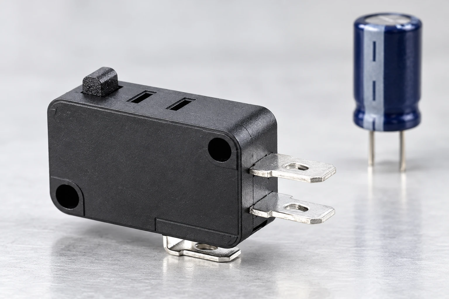
Understand the first charging interval
For an ideal, initially uncharged capacitor connected to a constant DC source through a resistance, the initial current is I(0) = V/R and the time constant is tau = RC. Use volts, ohms and farads to obtain amperes and seconds. The OpenStax explanation of RC charging provides the underlying model. Its practical purpose here is to show why a small steady load can still have a substantial initial demand.
For a hypothetical 24 V source, 12 ohms of total series resistance and 470 microfarads of capacitance, that ideal model gives 2 A initially and a 5.64 millisecond time constant. These are illustrative circuit inputs, not KW7 specifications, permissible contact currents or measured appliance results. A real design needs its actual impedance and supply response. Changing the assumed resistance strongly changes the estimate.
The model excludes contact bounce, wiring inductance, nonlinear current limiting, capacitor equivalent series resistance and an already charged input. It also does not calculate a contact’s permitted switching life. Use it to decide what must be measured and discussed. Do not turn a theoretical pulse into a pass result, or divide a catalog current rating by an arbitrary safety factor and call that a capacitive rating.
Keep closing stress separate from opening stress
Capacitor charging is principally a question about the connection event in this review. Inductive loads raise a different concern when their current path is interrupted. An electronic load can contain both behaviors, so label the events on the schematic. Our inductive-load switch guide explains the complementary opening-event review.
Contact bounce can produce multiple short events rather than one clean ideal closure. The contact bounce guide explains the distinction between a mechanical contact event and a processed control signal. Software filtering may prevent extra commands, but it does not remove the physical charging current passing through a power contact. Treat signal interpretation and contact loading as separate decisions.
A downstream fuse or protective device also needs its own coordination review. It should not be assumed to protect a small contact from every short startup pulse. Confirm the protective device behavior for its intended function and obtain component-specific evidence for the switch. This article does not prescribe fuse sizing, a suppression circuit or a protective arrangement for a particular machine.
Build a capture plan before choosing mitigation
Write down the event you need to observe: contact closing into the defined load, with known supply voltage and a known precharge condition. Specify the current probe or shunt arrangement, bandwidth, acquisition settings and trigger. The responsible engineer must choose safe measurement practices, isolation and equipment ratings. A diagram of where current is measured helps prevent a later comparison between unrelated signals.
Record the peak, pulse duration and waveform shape using an agreed definition. Include enough context to see repeated events, supply recovery and any bounce-related pulses. A slowly updating handheld meter may be useful for running current but cannot be assumed to reveal a brief peak. Preserve raw captures alongside the summarized values so the supplier can examine the actual evidence.
Define cold start, rapid restart and other credible sequences. A capacitor’s initial voltage can differ between them, while a limiter’s condition can also change. Identify the release interval and whether any discharge path is part of the controlled design. Do not deliberately short a charged capacitor to reset a test. Apply the load manufacturer’s discharge instructions and the approved laboratory procedure.
| Review input | Grabar | Decision supported |
|---|---|---|
| Suministro | Voltage range and current limiting | Reproduce the actual available source |
| Cargar | Circuit and input manufacturer data | Separate running load from startup |
| Initial state | Capacitor voltage and restart interval | Compare equivalent connection events |
| Waveform | Peak duration shape and raw capture | Describe actual closing demand |
| Mitigation | Controlled circuit revision and behavior | Review changes beyond peak reduction |
| Acceptance | Exact contact duty and agreed method | Avoid inferred capacitive ratings |
Compare mitigation as a system change
A series resistor, precharge arrangement, current-limited supply or separate power-switching stage may change the demand seen by the mechanical contact. Each option needs evaluation beyond its effect on the first peak. Ask about startup time, voltage available to the load, fault behavior, heating, restart conditions and the way control power is removed. A suitable solution must preserve the intended equipment behavior.
El MIT RC circuits lecture is useful background for understanding how circuit resistance and capacitance affect a transient. It is not an approval document for a switch or limiter. Have the engineer responsible for the assembly select and verify any circuit change, using the actual component data and relevant equipment requirements.
If the micro switch only needs to report position, consider whether it can operate a suitable control interface rather than directly energize the load. That changes the required review; it does not automatically make every small-signal combination suitable. Check the new input’s voltage, current, minimum-load compatibility and failure response. Keep the power stage’s selection and approval evidence alongside the revised circuit.
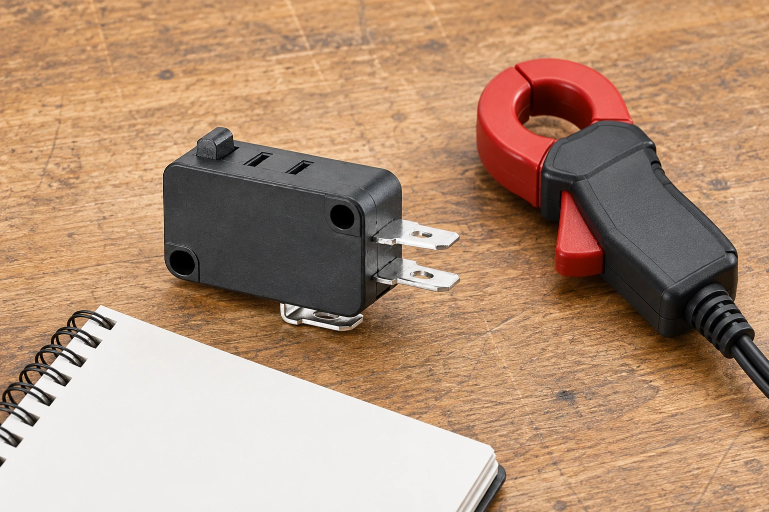
Validate useful switching life under defined conditions
An isolated successful startup proves only that the observed event occurred. It does not demonstrate a required service life. Establish the intended number and pattern of operations, operating speed, environment and acceptance criteria with the supplier before qualification. Keep the scope realistic for the application, and distinguish a development experiment from a release test performed under an approved method.
During evaluation, examine changes in contact behavior and the complete assembly, not only whether the load eventually starts. Investigate unexpected sticking, intermittent conduction, visible damage or excessive heating using safe procedures. The artículo de diagnóstico de contacto soldado proporciona un límite de fallo relacionado. No continúe ciclando un conjunto sospechoso simplemente para alcanzar un conteo objetivo.
Utiliza el Guía de vida eléctrica versus mecánica para enmarcar la discusión con el proveedor. La resistencia mecánica sin la carga eléctrica especificada no puede establecer la resistencia en el circuito capacitivo propuesto. Los cambios en la fuente de alimentación, el condensador de entrada, el cable o el limitador deben activar una revisión documentada para determinar si la evidencia existente sigue siendo representativa.
Enviar una consulta lista para tomar decisiones
Proporcione el código exacto del interruptor, revisión del dibujo, circuito de carga, rango de alimentación y forma de onda de arranque medida. Añada corriente en funcionamiento, secuencia de reinicio, vida útil requerida, entorno y método de aceptación propuesto. Indique qué información se mide, suministra el fabricante del carga o aún se asume. Esto permite a Lemaele identificar entradas faltantes y considerar si se necesita un contacto con un deber o arquitectura diferente soportada.
Solicite confirmación por escrito del uso propuesto y sus condiciones en lugar de una respuesta genérica de sí o no sobre amperajes. Si la carga requerida no es soportada, mantenga esa brecha y elija otra configuración con evidencia adecuada. El resultado de compra correcto es una decisión de aplicación rastreable, no un mayor corriente nominal impresa en un interruptor superficialmente similar.
Aprenda el principio del condensador
khanacademymedicine: Condensadores y capacitancia | Circuitos | Física | Khan Academy. Khan Academy explica la capacitancia como base para la revisión de carga de encendido. Esto no es una demostración de conmutación KW7 ni una clasificación de corriente de entrada permitida.

Ver Condensadores y capacitancia | Circuitos | Física | Khan Academy.
Preguntas frecuentes
¿Puede un controlador de baja potencia tener una alta corriente de entrada?
Sí. Su demanda de carga inicial puede diferir de su demanda en funcionamiento. Obtenga el comportamiento real de entrada y mida el evento relevante en lugar de seleccionar contactos solo por la energía estable.
¿Una clasificación de CA aprueba el mismo circuito de CC?
No coincida el voltaje soportado, la carga y las condiciones de conmutación con el circuito real. Solicite la evidencia de la variante exacta; una fuente de alimentación o un ciclo diferente requiere su propia revisión.
¿El software de rebote protegerá un contacto de potencia?
El software puede cambiar la forma en que un control interpreta los eventos. No elimina la corriente de carga física a través de un contacto que conecta la carga. Revise el estrés eléctrico por separado del procesamiento de señales.
¿Es suficiente el cálculo RC ideal para su liberación?
No. Describe un circuito simplificado y ayuda a planificar la investigación. Incluye el comportamiento real de la fuente, condiciones de reinicio, eventos de contacto y evidencia de aceptación respaldada por el proveedor antes de aprobar la solicitud.