
A micro switch capacitive load needs a closing-current review, even when its steady running current is small. Charging the load’s input capacitance can create a short current pulse that a normal running-current measurement misses. Select contacts against the exact voltage, circuit, switching duty and supported load evidence; do not assume a resistive-load marking also approves an electronic power input. This guide explains how an OEM can describe that pulse, examine practical mitigation options and prepare a useful supplier review without inventing a universal capacitive-load rating.
Identify what the switch actually energizes
Begin with the equipment schematic and the real load, rather than the name on the finished appliance. A switch that enables a logic input sees a different circuit from a switch that connects power to an electronic controller. Both assemblies may draw the same running current elsewhere in the machine. Trace the current through the contact during closing, normal operation and opening, including alternative supply paths and any input filtering.
List the supply voltage range, whether the switched path is AC or DC, the input capacitance where known, and the load manufacturer’s startup information. Include power-supply current limiting and cable resistance. If the load is a purchased module, ask its manufacturer for the relevant input behavior rather than estimating everything from the nameplate wattage. A switching power supply can present a more complicated input than a single ideal capacitor.
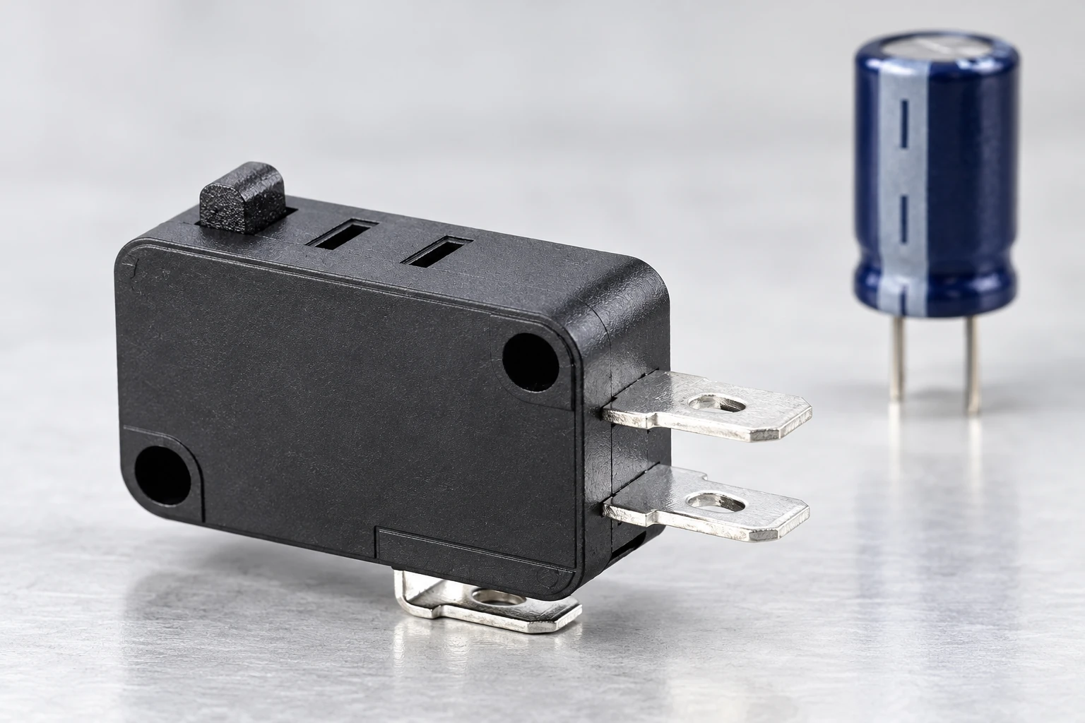
Das KW7 series product page is a starting point for identifying the physical switch family. Ask Lemaele to confirm the complete variant, terminal arrangement and supported electrical duty for your circuit. A family photograph or a headline current value does not establish a capacitive switching capability. Retain the exact drawing and approval conditions used in the review.
Understand the first charging interval
For an ideal, initially uncharged capacitor connected to a constant DC source through a resistance, the initial current is I(0) = V/R and the time constant is tau = RC. Use volts, ohms and farads to obtain amperes and seconds. The OpenStax explanation of RC charging provides the underlying model. Its practical purpose here is to show why a small steady load can still have a substantial initial demand.
For a hypothetical 24 V source, 12 ohms of total series resistance and 470 microfarads of capacitance, that ideal model gives 2 A initially and a 5.64 millisecond time constant. These are illustrative circuit inputs, not KW7 specifications, permissible contact currents or measured appliance results. A real design needs its actual impedance and supply response. Changing the assumed resistance strongly changes the estimate.
The model excludes contact bounce, wiring inductance, nonlinear current limiting, capacitor equivalent series resistance and an already charged input. It also does not calculate a contact’s permitted switching life. Use it to decide what must be measured and discussed. Do not turn a theoretical pulse into a pass result, or divide a catalog current rating by an arbitrary safety factor and call that a capacitive rating.
Keep closing stress separate from opening stress
Capacitor charging is principally a question about the connection event in this review. Inductive loads raise a different concern when their current path is interrupted. An electronic load can contain both behaviors, so label the events on the schematic. Our inductive-load switch guide explains the complementary opening-event review.
Contact bounce can produce multiple short events rather than one clean ideal closure. The contact bounce guide explains the distinction between a mechanical contact event and a processed control signal. Software filtering may prevent extra commands, but it does not remove the physical charging current passing through a power contact. Treat signal interpretation and contact loading as separate decisions.
A downstream fuse or protective device also needs its own coordination review. It should not be assumed to protect a small contact from every short startup pulse. Confirm the protective device behavior for its intended function and obtain component-specific evidence for the switch. This article does not prescribe fuse sizing, a suppression circuit or a protective arrangement for a particular machine.
Build a capture plan before choosing mitigation
Write down the event you need to observe: contact closing into the defined load, with known supply voltage and a known precharge condition. Specify the current probe or shunt arrangement, bandwidth, acquisition settings and trigger. The responsible engineer must choose safe measurement practices, isolation and equipment ratings. A diagram of where current is measured helps prevent a later comparison between unrelated signals.
Record the peak, pulse duration and waveform shape using an agreed definition. Include enough context to see repeated events, supply recovery and any bounce-related pulses. A slowly updating handheld meter may be useful for running current but cannot be assumed to reveal a brief peak. Preserve raw captures alongside the summarized values so the supplier can examine the actual evidence.
Define cold start, rapid restart and other credible sequences. A capacitor’s initial voltage can differ between them, while a limiter’s condition can also change. Identify the release interval and whether any discharge path is part of the controlled design. Do not deliberately short a charged capacitor to reset a test. Apply the load manufacturer’s discharge instructions and the approved laboratory procedure.
| Review input | Aufnehmen | Decision supported |
|---|---|---|
| Versorgung | Voltage range and current limiting | Reproduce the actual available source |
| Laden | Circuit and input manufacturer data | Separate running load from startup |
| Initial state | Capacitor voltage and restart interval | Compare equivalent connection events |
| Waveform | Peak duration shape and raw capture | Describe actual closing demand |
| Mitigation | Controlled circuit revision and behavior | Review changes beyond peak reduction |
| Acceptance | Exact contact duty and agreed method | Avoid inferred capacitive ratings |
Compare mitigation as a system change
A series resistor, precharge arrangement, current-limited supply or separate power-switching stage may change the demand seen by the mechanical contact. Each option needs evaluation beyond its effect on the first peak. Ask about startup time, voltage available to the load, fault behavior, heating, restart conditions and the way control power is removed. A suitable solution must preserve the intended equipment behavior.
Das MIT RC circuits lecture is useful background for understanding how circuit resistance and capacitance affect a transient. It is not an approval document for a switch or limiter. Have the engineer responsible for the assembly select and verify any circuit change, using the actual component data and relevant equipment requirements.
If the micro switch only needs to report position, consider whether it can operate a suitable control interface rather than directly energize the load. That changes the required review; it does not automatically make every small-signal combination suitable. Check the new input’s voltage, current, minimum-load compatibility and failure response. Keep the power stage’s selection and approval evidence alongside the revised circuit.
Validate useful switching life under defined conditions
An isolated successful startup proves only that the observed event occurred. It does not demonstrate a required service life. Establish the intended number and pattern of operations, operating speed, environment and acceptance criteria with the supplier before qualification. Keep the scope realistic for the application, and distinguish a development experiment from a release test performed under an approved method.
During evaluation, examine changes in contact behavior and the complete assembly, not only whether the load eventually starts. Investigate unexpected sticking, intermittent conduction, visible damage or excessive heating using safe procedures. The Schweißkontakt-Diagnoseartikel bietet eine zugehörige Fehlergrenze. Fahren Sie nicht fort, eine verdächtige Baugruppe nur, um eine Zielanzahl zu erreichen.
Benutzen Sie Elektromotorisches versus mechanisches Lebensdauerleitfaden Um die Lieferantendiskussion zu rahmen. Mechanische Dauerfestigkeit ohne die angegebene elektrische Last kann keine Dauerfestigkeit im vorgeschlagenen kapazitiven Stromkreis nachweisen. Änderungen an der Stromversorgung, Eingangskondensator, Kabel oder Begrenzung sollten eine dokumentierte Überprüfung auslösen, ob die vorhandenen Nachweise weiterhin repräsentativ sind.
Senden Sie eine einsatzbereite Anfrage
Geben Sie den genauen Schaltcode, die Zeichnungsrevision, den Lastkreis, den Versorgungsspannungsbereich und die gemessene Anlaufwellenform an. Fügen Sie den Betriebsstrom, den Neustartablauf, die erforderliche Lebensdauer, die Umgebung und die vorgeschlagene Akzeptanzmethode hinzu. Geben Sie an, welche Informationen gemessen, vom Lasthersteller bereitgestellt oder noch angenommen werden. Dies ermöglicht es Lemaele, fehlende Eingaben zu identifizieren und zu prüfen, ob ein anderer unterstützter Kontaktbetrieb oder eine andere Architektur erforderlich ist.
Bitten Sie um schriftliche Bestätigung des vorgeschlagenen Einsatzes und seiner Bedingungen, anstatt eine allgemeine Ja-oder-Nein-Antwort bezüglich Ampere zu geben. Wenn die erforderliche Betriebsart nicht unterstützt wird, behalten Sie diese Lücke bei und wählen Sie eine andere Anordnung mit entsprechenden Nachweisen. Das richtige Einkaufsergebnis ist eine nachvollziehbare Anwendungsentscheidung, nicht eine höhere Nennstromangabe auf einem oberflächlich ähnlichen Schalter.
Lernen Sie das Kondensatorprinzip
khanacademymedicine: Kondensatoren und Kapazität | Schaltungen | Physik | Khan Academy. Khan Academy erklärt die Kapazität als Hintergrund für die Überprüfung der Ladebelastung. Dies ist keine KW7-Schaltdemonstration oder eine zulässige Einschaltstrombegrenzung.

Sehen Sie sich Kondensatoren und Kapazität | Schaltungen | Physik | Khan Academy an.
Häufig gestellte Fragen
Kann ein Niedrigleistungs-Controller einen hohen Einschaltstrom haben?
Ja. Sein anfänglicher Ladebedarf kann vom laufenden Bedarf abweichen. Erfassen Sie das tatsächliche Eingangsverhalten und messen Sie das relevante Ereignis, anstatt Kontakte nur bei konstanter Leistung auszuwählen.
Genehmigt eine AC-Bewertung den gleichen DC-Kreis?
Nummer. Stimmen Sie die unterstützte Spannung, Last- und Schaltbedingungen mit dem tatsächlichen Stromkreis ab. Fragen Sie nach dem genauen Variantenbeleg; eine andere Versorgung oder Aufgabe erfordert eine eigene Überprüfung.
Wird die Software-Entprellung einen Leistungskontakt schützen?
Software kann beeinflussen, wie eine Steuerung Ereignisse interpretiert. Es entfernt nicht den physischen Ladestrom durch einen Kontakt, der die Last schaltet. Überprüfen Sie die elektrische Belastung separat von der Signalverarbeitung.
Ist die ideale RC-Berechnung ausreichend für die Freigabe?
Nein. Es beschreibt einen vereinfachten Schaltkreis und unterstützt die Planung der Untersuchung. Einschließlich des tatsächlichen Versorgungverhaltens, Neustartbedingungen, Kontaktereignissen und vom Lieferanten unterstütztem Akzeptanznachweis vor der Freigabe der Anwendung.