
Micro switch welded contacts are a specific failure in which a contact connection remains closed when the mechanism should have opened it. A stuck machine input is not enough to prove welding: bridged wiring, a damaged cable, incorrect terminal identification or a mechanically held actuator can produce a similar symptom. Isolate the equipment, preserve the original condition and establish the failure boundary before deciding what happened. A suspect welded contact should not be forced back into service by tapping, bending or repeatedly cycling the switch.
This guide explains an evidence-preserving investigation and recurrence review for ordinary OEM switching. The LEMA KW7 product family supplies a real reference for discussing model identity and contact duty. It does not establish that an illustrated sample has welded contacts or that any model is suitable for a safety function.
Define what remained closed
Begin with the expected electrical function. Identify common, normally open and normally closed terminals from the exact drawing and an isolated state check. Establish whether the reported path should be open at the observed actuator position. A terminal-number assumption copied from another switch can create a false failure report.
Distinguish the physical contact state from the controller display. An input may remain active because of wiring, leakage, a parallel path or the controller logic. Record the actual observation without naming the internal failure prematurely. “Input remained on after target withdrawal” is useful evidence; “contacts welded” is a conclusion that still needs support.
El isolated multimeter guide explains the basic identification check. It does not replace a controlled investigation of a loaded circuit or authorize live probing.
Make the investigation safe before disconnecting parts
A contact that fails to open may leave an unexpected load energized. Follow the equipment’s isolation procedure and verify the safe condition before touching conductors or moving the mechanism. Control stored and non-electrical energy as well as the electrical supply where those hazards exist.
El OSHA control-of-hazardous-energy guidance explains the servicing boundary. Do not rely on the suspect switch as the isolation device. A control contact and an energy-isolating device perform different functions.
Photograph the original installation, markings, connections and actuator position before removal when it is safe to do so. Record the date, equipment state and recent events. Disconnect and identify conductors under the approved procedure so the sample can later be related to the actual circuit.
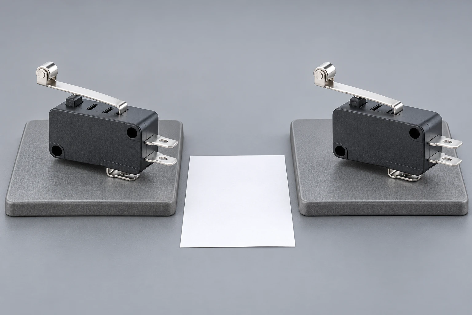
Separate mechanical holding from an electrical stuck-closed path
Confirm that the external target has withdrawn and that the actuator is free to return as intended. Binding, a bent lever, a loose bracket or excessive overtravel can hold a switch operated. These conditions do not establish that the contact surfaces have welded.
After safe isolation and disconnection from other circuit paths, check the relevant terminal state at the defined actuator positions. Record the instrument, range and connection points. A meter reading must be interpreted with the circuit boundary understood; an unexpected parallel connection can defeat an otherwise careful test.
If the isolated switch remains electrically closed while its actuator has returned, classify the observation accurately and preserve the sample. Do not open the housing simply to obtain a dramatic photograph. Internal examination may destroy evidence and should follow the supplier’s agreed failure-analysis process.
Understand why a headline rating is insufficient
Contact duty depends on more than a single current number. Supply type, voltage, load behavior, inrush, switching sequence and operating rate can affect the electrical stress. A steady resistive current is not an adequate description of every motor, lamp, capacitor or coil circuit.
Obtain the exact switch rating and its conditions, then compare them with the actual load record. A component’s mechanical operating life does not establish electrical life under another circuit. Likewise, a contact that passes a no-load continuity check has not demonstrated that it can interrupt the intended duty.
El inductive-load selection article addresses load matching and protection questions. The present investigation asks whether a particular stuck-closed symptom is internal, what evidence supports the diagnosis and what must change before release.
Collect the events surrounding the failure
Ask when the fault appeared: first power-up, load connection, normal cycling, a jam, a supply disturbance or a recent component change. Record the actual load part number and circuit revision. Include protection devices and any suppression components, with their identity and connection arrangement.
Do not assume that a suppression component is correct because it is present. Its suitability depends on the circuit, switching behavior and required release timing. An improvised diode or network can introduce another problem. Changes to the load or protection should be reviewed by the responsible electrical engineer.
Where measurements are required, use a controlled procedure capable of capturing the relevant event. A slow average-current reading may miss a short inrush. Avoid producing new damage by repeatedly energizing the suspect assembly to reproduce an event without an approved test plan.
Preserve a meaningful failure sample
Keep the suspect switch separate from unfailed comparison parts. Label its identity, equipment location and removal condition in the maintenance record. Retain relevant connectors or cable sections when they may be part of the fault, without mixing their original relationships.
Do not clean, lubricate, file or manually separate internal contacts before the analysis route is agreed. Such actions can alter contact surfaces and obscure whether the observed condition resulted from the original event or the later handling. Record any actions already taken, including repeated cycling.
El NASA technical-report record on long-life EEE hardware reliability is background for treating contact behavior as a reliability investigation, not a product-specific LEMA test result. Use the supplier’s actual analysis and the equipment evidence to reach the final conclusion.
| Finding | What it establishes | Next boundary |
|---|---|---|
| Controller input remains active | A system symptom | Check logic wiring and actual actuator state |
| Target still holds actuator | Mechanical operation may remain commanded | Inspect target clearance and return |
| Isolated contact stays closed after actuator return | A persistent switch-side electrical observation | Preserve sample and arrange analysis |
| Replacement works briefly then repeats | Original stress may remain | Review load protection and mechanical configuration |
| Physical sample was opened or cleaned | Evidence has been altered | Record handling before interpreting analysis |
Correct the cause before approving a replacement
Installing another identical switch may restore function temporarily while leaving the same electrical stress or mechanical fault. Compare the original and proposed configuration before restarting production. Identify whether the correction concerns the load interface, protection, actuator arrangement, wiring or the switch selection itself.
A higher printed current value is not a complete corrective action. The proposed component still needs the correct AC or DC duty, load category, connection method, operating sequence and mechanical fit. Where direct load switching is unsuitable, a properly selected interface device may be part of the design review, but its suitability must be established for the application.
For model substitution, use the micro switch replacement guide. Keep the electrical recurrence review with that form-and-fit comparison so a mechanically interchangeable part is not mistaken for an electrically approved replacement.
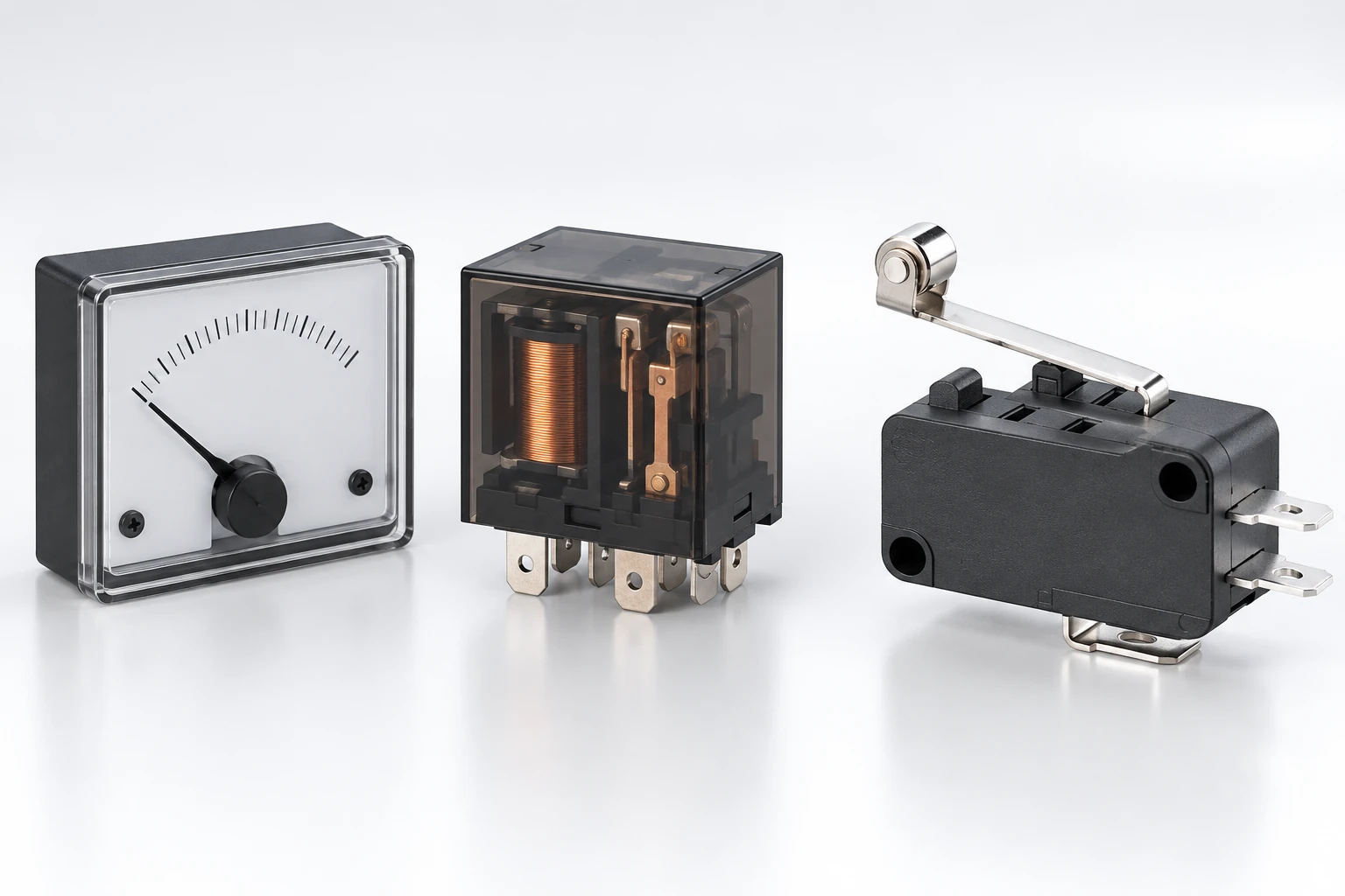
Validate the corrected circuit under an agreed plan
Define the acceptance criteria before collecting new results. Identify the switch and load revisions, supply conditions, protection arrangement, operating rate, environmental conditions and samples. Include the events believed to have caused the original stress, using a safe and technically justified procedure.
Record electrical performance and the complete mechanical operation. A change in the target or mounting can affect contact behavior, while a circuit change can affect the machine response. Confirm the intended opening and closing sequence and the equipment-level result, not only that a replacement clicks.
State the limits of the test. A short functional check is not an endurance qualification. If the risk or duty requires longer testing, the plan should say so explicitly. Do not convert a few successful operations into an unsupported lifetime claim.
Send a useful supplier investigation request
Provide the complete order code, lot identification when available, quantities affected, circuit diagram, load information, installation photographs and the exact isolated observations. Distinguish confirmed facts from suspected causes. Include the removed sample’s handling history and any comparison measurements.
Ask for the analysis route, the evidence required and the conditions under which a replacement can be evaluated. A useful response may require the physical sample and equipment information; the exterior photograph alone cannot establish an internal weld mechanism.
Utiliza el LEMA inquiry page for a documented discussion of the actual circuit. The broader failure-mode guide remains useful for other symptoms, while this record should stay focused on the stuck-closed path and its verified correction.
Further learning: normal position-switch operation
RealPars: Limit Switch Explained | Working Principles. RealPars explains normal position-switch operation. Use that general educational explanation to distinguish actuator motion and contact state; it does not diagnose a welded sample or approve a particular LEMA load.
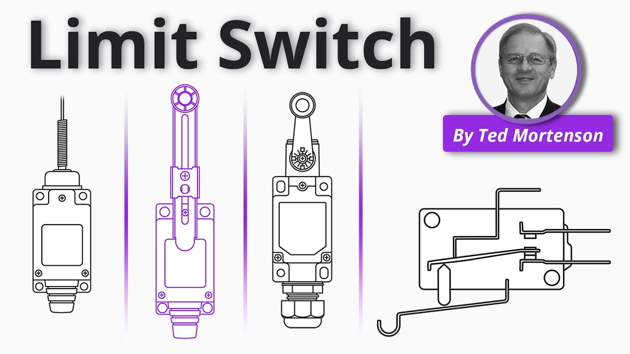
Watch Limit Switch Explained | Working Principles.
Preguntas frecuentes
Does a stuck PLC input prove contacts are welded?
No. Wiring, parallel paths, input behavior and a mechanically held actuator can produce the same report. Establish the safe isolated boundary and the actual terminal state before assigning an internal failure mechanism.
Can I tap a stuck switch until it opens?
That can change the evidence and does not establish reliable service behavior. Remove the suspect assembly from use under the equipment procedure, preserve its condition and follow the agreed failure-analysis and replacement process.
Will a higher current label prevent recurrence?
A label alone is insufficient. Compare the actual AC or DC load, inrush, switching conditions, protection and duty with the proposed component evidence. The correction must address the verified stress or mechanical problem.
Should I open the housing before returning the sample?
Only under the agreed investigation process. Opening, cleaning or manually separating contacts may alter the surfaces and obscure the cause. Preserve the removed sample and document any handling already performed.