
Toggle switch mounting bushing roundness inspection must begin with a defined surface and an agreed drawing requirement. An external thread, a smooth locating land, a panel hole, and the rotating handle are different features. A few caliper readings or a tight mounting nut cannot establish the roundness of all of them. Identify the ordered switch, specify the inspection section, and select a measurement method suited to that feature before judging the result. This guide helps buyers separate shape, size, thread fit, and mounting problems, so they request evidence that can actually resolve an assembly concern.
Why the measured feature matters
A threaded mounting bushing has several surfaces with different purposes. Its thread engages mounting hardware; a shoulder or locating feature may interact with the panel; the handle passes through the upper assembly. The visible outline of the thread is not one uninterrupted smooth circle. A report that merely says bushing roundness checked leaves the reader unable to tell which of those surfaces was measured.
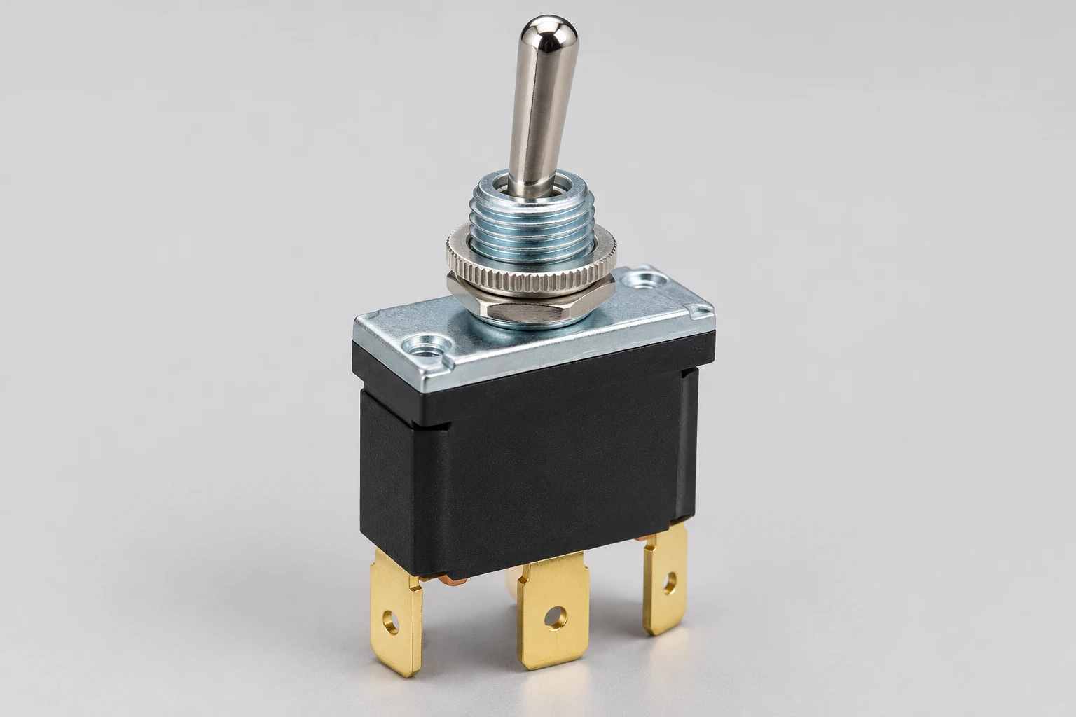
Para el Lemaele LT3230C toggle switch, use the ordered drawing and approved mounting hardware to identify the feature of interest. The product photograph establishes the family’s visible arrangement, not a geometric tolerance. Do not assign a roundness limit or select a thread gauge from an image filename, apparent scale, or a similar-looking switch.
Separate roundness, diameter, and runout
Diameter describes size according to a measurement definition. Roundness evaluates the form of a circular profile. Runout involves a relationship to an axis and a rotation setup. These questions can overlap in an investigation, but their results are not interchangeable. A component can satisfy selected size readings while still needing a more complete form assessment, and a runout reading can include effects that are not simply out-of-roundness.
El NIST single-trace roundness explanation describes a profile-based method and notes the contribution of spindle error to the observed deviations. This is useful background for reviewing a report. It does not prescribe an LT3230C inspection method or authorize treating an ordinary caliper as a roundness instrument. The checklist below separates the decisions before measurement begins.
| Evidence item | Qué verificar | Decision supported |
|---|---|---|
| Size concern | Define diameter, location and contact method | Check the intended dimensional requirement |
| Roundness concern | Identify a complete accessible circular profile | Evaluate the specified form characteristic |
| Thread engagement | Confirm thread and mating hardware identity | Review engagement by the agreed method |
| Runout concern | Identify reference axis and rotation setup | Avoid confusing axis effects with form |
| Installation concern | Record panel, coating and hardware stack | Investigate the complete mounting interface |
Do not measure across a thread as though it were a plain cylinder
Thread crests, roots, start position, and the contact geometry of a measuring tool affect what a reading represents. Two measurements across an external thread may be useful for a defined size check, but they do not automatically provide a complete roundness result. If the assembly concern is engagement with a nut, begin with the specified thread designation, hardware identity, and applicable thread verification method.
When the requirement concerns a smooth locating surface, identify its axial position and accessible inspection band. If no such surface exists, ask the drawing owner what feature the requested form control applies to. Avoid inventing a convenient cylindrical band on a finished assembly. The supplier may need to provide manufacturing-stage evidence or an alternative measurement strategy for an inaccessible feature.
Record the mounting symptom without guessing its cause
Describe whether the switch will not enter the panel, rocks before tightening, rotates after installation, or develops unusual nut resistance. Record the panel drawing, cutout condition, coating, hardware stack, and ordered switch version. These observations guide the investigation without declaring that a circular-form defect is responsible. Preserve the received condition before applying force or modifying the panel.
For example, a nut that starts unevenly may indicate a hardware or engagement problem requiring review. It does not prove that the bushing is oval. The mounting thread galling guide addresses a different potential mechanism, while the mounting nut tightening guide covers assembly control. Use each investigation for its actual question rather than folding every symptom into roundness.
Choose an inspection method with the supplier
The correct method depends on the defined feature, accessible geometry, required sensitivity, and acceptance rule. Discuss a suitable profile instrument, optical approach, or agreed functional check with the responsible metrology team. A functional check can be valuable for assembly acceptance when specified, but label it as a functional result. It does not become a geometric measurement because the part assembled successfully.
If a report uses a fitted circle, ask what profile was captured and how the reference was established. Request the section location, setup, filtering or evaluation settings where relevant, and the instrument identity. The report should make it possible to repeat the measurement. A single number without the feature definition cannot explain whether two suppliers measured the same characteristic.
Control fixturing and measurement error
Support the switch so the setup does not damage the housing, terminals, bushing, or handle. Clamping a small assembly can introduce position changes or deformation; the laboratory should justify its holding method and repeatability. Never force a stylus into an inaccessible area or use the handle as an improvised precision spindle. Keep electrical connections disconnected during mechanical inspection.
NIST’s multiple-trace roundness discussion explains how repeated traces with changed orientation can separate instrument and artifact contributions in its calibration context. The procurement lesson is limited but important: ask how measurement-system effects were addressed when they matter to the decision. Do not copy the research procedure directly onto an assembled switch without a justified method.
Make reports from different parties comparable
Before comparing numbers, compare the feature, section, reference, units, instrument method, and evaluation settings. A reading across thread crests is not comparable to a profile of a smooth shoulder. A result taken at the top of a feature is not necessarily equivalent to one close to the mounting plate. Require clear identification of where the data came from.
Retain the raw profile or images when available, rather than only a rounded summary value. Ask the laboratory to state uncertainty or measurement capability in a form appropriate to the acceptance decision. If the result sits close to the agreed limit, follow the contract’s decision rule and seek clarification. Do not create a universal extra allowance or subtract uncertainty opportunistically to obtain a preferred outcome.
Keep the panel and hardware in the investigation
A complete mounting assessment includes the panel opening, coating condition, locating features, washers, nuts, and assembly sequence. A switch feature can be within its requirement while an incompatible hardware stack prevents correct seating. Conversely, a favorable fit in one unusually generous panel does not establish conformity to the drawing. Inspect the interface as a system while keeping each component’s requirement separate.
Utiliza el toggle switch replacement guide as the broader compatibility checklist. Do not alter the bushing, chase threads, file the panel, or substitute nuts to make a questioned unit pass an informal trial. If an engineering-approved modification is necessary, document it as a controlled change with its own verification rather than silently accepting the original configuration.
A practical supplier inquiry and disposition
Send the part designation, drawing revision, lot identity, affected quantity, photographs, panel and hardware references, and a precise symptom description. State whether you need confirmation of a specified roundness characteristic, thread compliance, overall mounting fit, or a root-cause investigation. Ask the supplier to identify the measured surface before promising a particular report. This prevents both sides spending time on a number that answers the wrong question.
If conformity cannot yet be established, hold the identified material and agree the next evidence step. Separate temporary use authorization from permanent drawing approval. Record who owns the decision, which samples were inspected, and what action closes the concern. A supplier’s photograph of a different model or a statement that a nut feels smooth does not resolve a geometric requirement on your ordered feature.
Prepare repeatable requirements for the next purchase
For recurring orders, define the characteristic only where it serves a real installation need. Give the relevant drawing reference, inspection surface, required report content, sampling agreement, and acceptance responsibility. Coordinate with the manufacturer before imposing a form control on a surface that was never intended to act as a precision locator. The simplest useful requirement is one that is unambiguous, measurable, and connected to the assembly function.
Consider a hypothetical panel that rejects a switch while the approved nut threads on freely. The next useful comparison is the actual panel opening and the specified mounting envelope, followed by the defined bushing feature if needed. Repeatedly measuring arbitrary diameters across the thread would not establish the cause. A well-framed inspection ends with a result tied to the requirement and preserves the distinction between size, circular form, thread engagement, and complete mounting fit.
Formación continua
NPTEL’s lesson on fits and geometrical tolerances explains the distinction between dimensional requirements and geometric controls. It supports planning the inspection question; it does not specify tolerances for a Lemaele switch.

Preguntas frecuentes
Can a caliper prove bushing roundness?
Selected caliper readings provide size information under their measurement conditions. They do not automatically establish a complete circular profile or satisfy a separately specified roundness requirement.
Does a tight nut show the bushing is oval?
No. Hardware identity, thread damage, engagement and assembly conditions also require review. Record the symptom and verify the specified interface before attributing it to roundness.
Where should an LT3230C roundness limit come from?
From the agreed drawing or specification for the exact ordered feature. This article does not assign a numerical limit or assume that the product has a precision smooth locating band.
What makes two reports comparable?
They must refer to the same feature, section, measurement definition and compatible evaluation method, with units and setup recorded. A thread-crest size result and a smooth-surface roundness trace answer different questions.