
A limit switch is used to detect when a moving machine part reaches a defined position and to send a discrete electrical signal to a control circuit. Common uses include end-of-travel detection, door or guard position monitoring, conveyor item detection, indexing confirmation, valve position feedback and cycle sequencing. The device does not measure continuous distance; its actuator changes contact state after physical movement. Correct selection depends on the target motion, actuator geometry, operating and release points, overtravel, contact logic, electrical load, environment and mounting tolerance. A general-purpose limit switch must not be assumed to perform a safety function unless the complete safety system is designed and validated for that purpose.
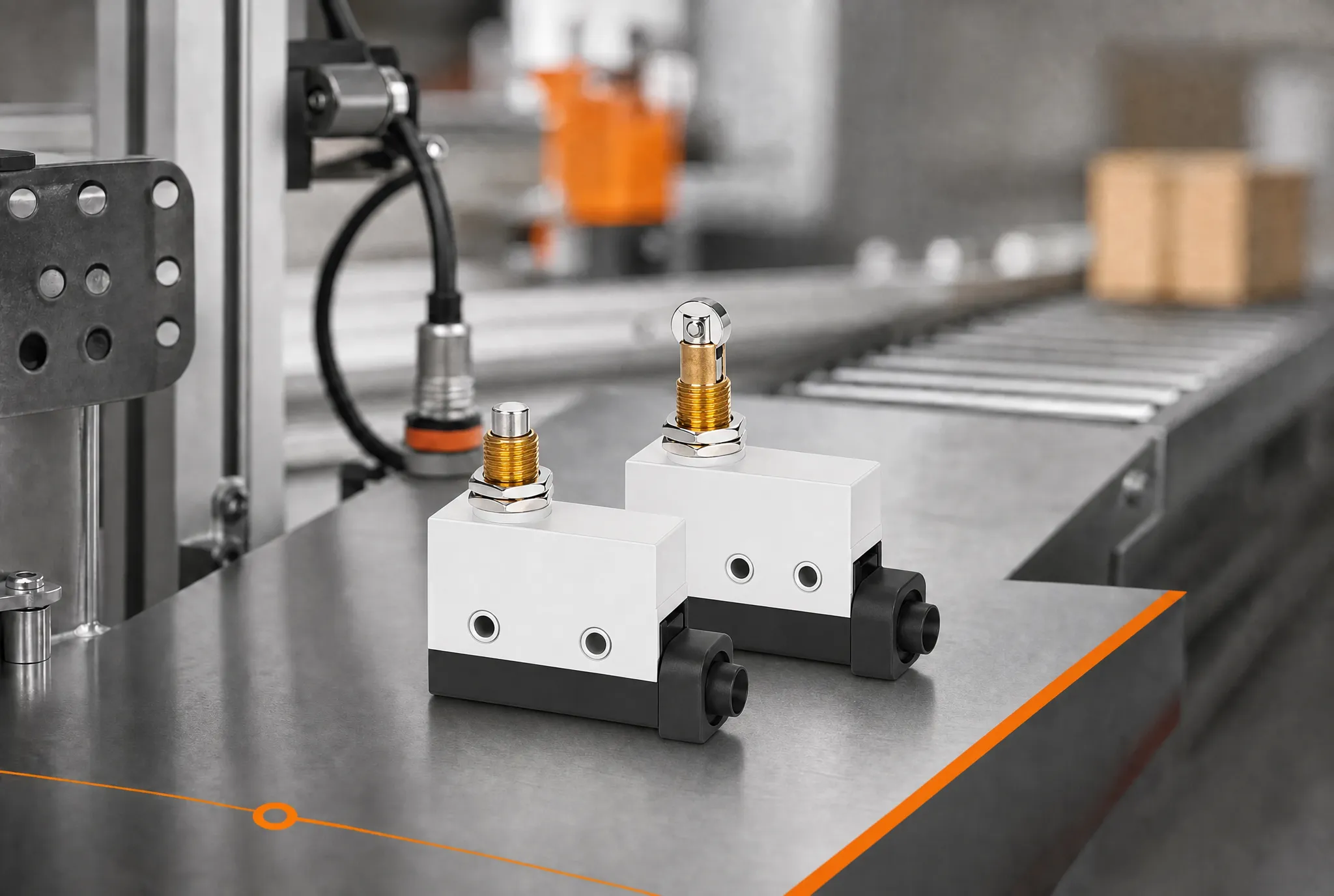
Where are limit switches used?
On conveyors, a roller lever can confirm that a carrier or package has reached a transfer point. On machine tools, a plunger or roller can report that a slide is home or at a travel boundary. On doors and covers, the signal may tell a controller whether a movable element is closed. Valves, dampers and material-handling mechanisms use switches to confirm fully open, fully closed or intermediate positions. Packaging and assembly machines use them to verify that a mechanism completed one step before the next begins.
The same physical event can serve different control purposes. A home signal establishes a reference, an end-of-travel signal prevents commanded motion beyond a working range, and a presence signal confirms that an object arrived. Write the purpose in plain language before choosing hardware because the required repeatability, response, failure behavior and controller logic are different.
How does the switching mechanism work?
The target contacts a plunger, lever, roller, rod or cam. Mechanical travel is transferred to an internal snap-action or switching mechanism, which changes one or more electrical contacts. The operating point is where the contact first changes state. The release point is where it returns as the target moves away. The difference between those positions helps prevent unstable switching but must be included in the machine tolerance calculation.
The actuator should approach in the direction and speed supported by the selected model. A roller lever can accommodate sweeping motion, while a direct plunger usually needs controlled axial movement. A long lever changes force and travel relationships. Never assume that an actuator fitted to a similar housing has the same permissible force, angle or overtravel.
Application and selection matrix
| Application | Detected event | Typical actuator concern |
|---|---|---|
| Conveyor | Product or carrier reaches a station | Target speed, angle and roller wear |
| Machine axis | Slide reaches home or travel boundary | Stopping distance and overtravel |
| Door or cover | Movable panel reaches closed position | Alignment, tampering and reset margin |
| Valve or damper | Mechanism reaches open or closed state | Cam profile and backlash |
| Packaging cycle | Mechanism completes a sequence step | Repeatability and contamination |
This decision table is qualitative because operating limits must come from the exact model drawing and the equipment documentation. Reject any proposed part whose actuator, contact arrangement, environmental boundary or dimensional interface remains ambiguous.
Define operating point, release point and overtravel
Start with the earliest and latest target positions allowed by the machine. Add target variation, bracket tolerance, actuator variation, structural deflection, wear and stopping distance. The switch must operate before the unacceptable condition while retaining enough additional travel for reliable actuation. At the opposite direction, it must release with adequate clearance rather than hovering at the transition point.
Test slow and normal approaches because dynamic deflection and stopping distance can change the result. Do not use the switch body as the target stop. If the mechanism can continue moving after contact, provide controlled overtravel and a separate stop consistent with the equipment design.
Contact logic and electrical load
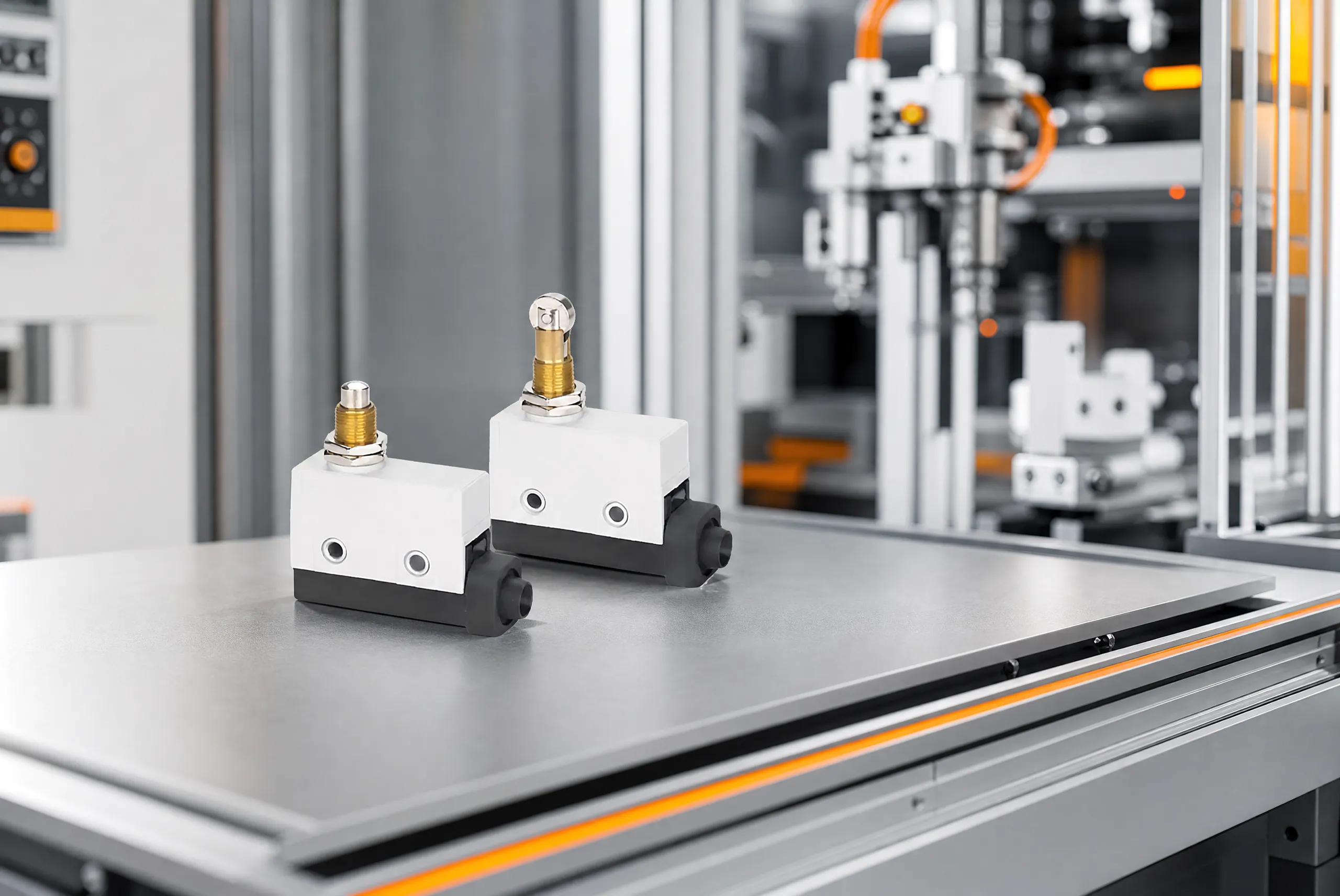
Many industrial limit switches provide COM, normally open and normally closed terminals. “Normal” refers to the defined unactuated condition, not the usual operating state of the machine. Trace the diagram for the exact part and verify continuity before energizing. Decide how the controller should interpret an open conductor, because a broken wire can resemble an unoperated NO circuit or an operated NC circuit.
Confirm voltage, AC or DC, resistive or inductive load, inrush, switching frequency and low-level signal suitability. A headline ampere rating is not transferable to every load. Use an interposing relay or suitable input architecture where required, and coordinate suppression with the control designer.
Mounting, alignment and environmental review
A rigid bracket is essential for repeatable position sensing. Record hole locations, orientation, hardware, adjustment range and tightening method. The target should contact the intended actuator surface without side load, sharp impact or scraping. Leave space for cable bends, gland access, terminal inspection and future replacement.
Describe dust, oil, chips, water, cleaning chemicals, temperature, vibration and outdoor exposure. An enclosure rating applies only under its stated installation conditions. Cable entry, cover sealing, conduit, mounting damage and maintenance practice influence the assembled result. Inspect the complete installation rather than relying on one catalogue code.
Installation and commissioning workflow
- Follow the site’s hazardous-energy control procedure and verify a safe condition.
- Match the model, actuator, terminal diagram and drawing revision to the approved record.
- Inspect the bracket, target, fasteners, cable entry and available travel.
- Mount and align the switch without distortion or actuator preload beyond the intended setup.
- Terminate wiring with controlled strip length, insulation clearance and strain relief.
- Test contact state and transition without power through the full mechanical movement.
- Check the controller indication, then test machine response at reduced speed and controlled risk.
- Record the accepted operating point, release point, final clearance and inspection method.
El Guía de energía peligrosa de OSHA explains the need for an established energy-control program during servicing. OSHA’s machine-guarding introduction provides context for hazards around moving machinery. For hoisting equipment, review OSHA 1910.179 together with the equipment manufacturer’s instructions and the requirements that apply in the installation location.
Inspection and troubleshooting
Inspection should look beyond whether the machine stopped once. Check loose mounting, bent levers, worn rollers, sticky plungers, cracked housings, damaged seals, cable strain and contamination. Operate the mechanism through its complete permitted travel and confirm both actuation and reset. Compare the trip position with the documented acceptance window.
If the controller state is wrong, separate the problem into three layers. First test the switch contacts without power. Next check the conductor and input state at the controller. Finally check the program logic and output response. This sequence avoids replacing a good switch when the actual issue is alignment, wiring or inverted logic.
Common mistakes
- Selecting by housing appearance instead of the complete part number.
- Confusing a working travel endpoint with a safety-rated protective function.
- Ignoring stopping distance, backlash, tolerance and wear.
- Applying a current rating to an unsupported voltage or load type.
- Using the actuator or housing as a hard mechanical stop.
- Mounting on a flexible bracket that changes the operating point.
- Testing actuation but not release, reset and fault behavior.
Lista de verificación de solicitudes de cotización para OEM
An effective RFQ states the equipment function, target motion and speed, normal and operated states, required operating window, permissible overtravel, actuator preference, mounting drawing, electrical load, cable or terminal style, environment, expected cycles, quantity, target market and validation method. Ask the supplier to return one complete part number and controlled drawing with deviations marked.
Sample approval should include critical dimensions, contact states, force and travel where relevant, environmental inspection and repeatability in the real bracket. Define production checks, traceability and change notification before volume purchase. This turns an acceptable sample into a repeatable supply requirement.
Recursos relacionados de LEMA
Revisar el LEMA limit switch range y el WL Series general limit switch. Continúa con el SPDT limit switch selection guide, roller limit switch applications guide y limit switch sourcing guide for adjacent design and purchasing questions.
Video: limit switch operating principle
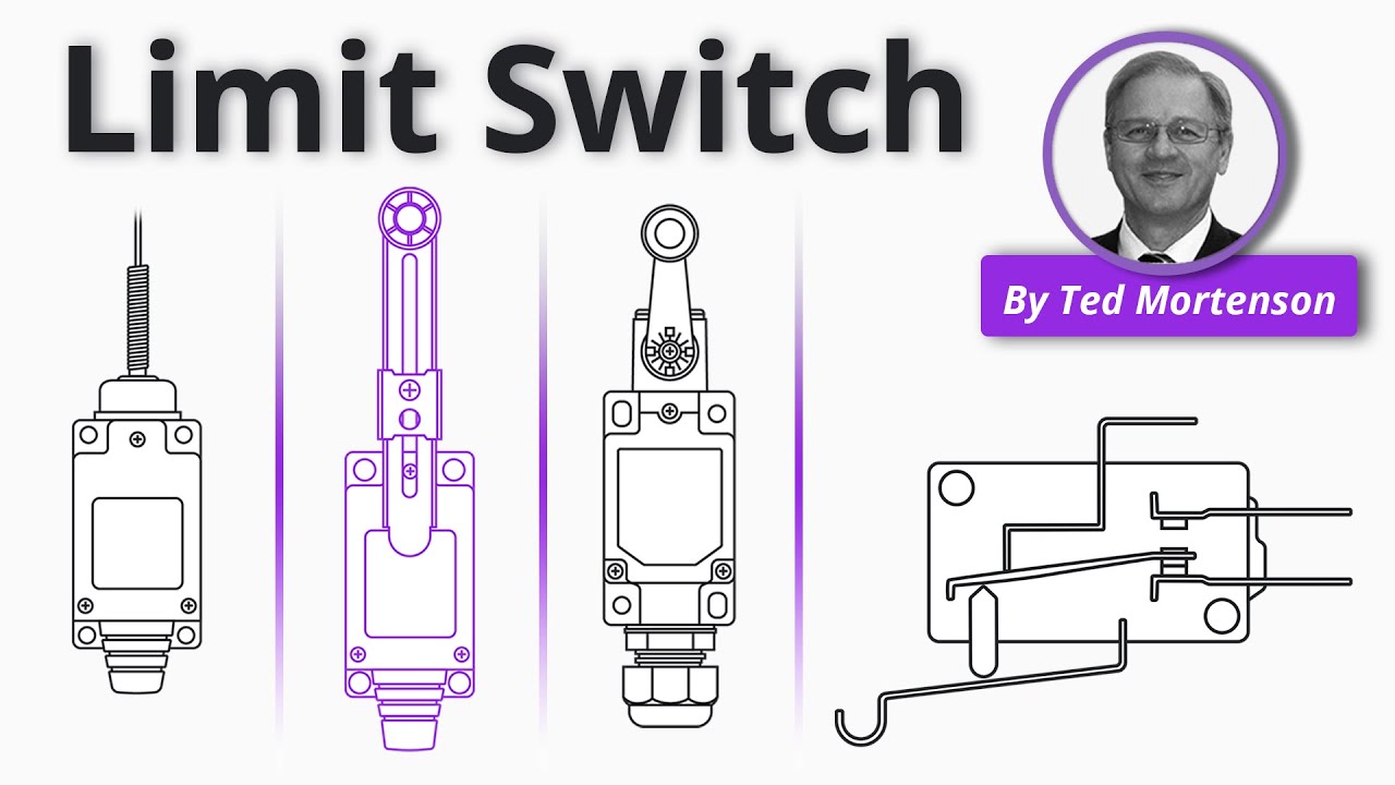
RealPars provides a neutral visual explanation of the mechanical and electrical operating principle. It is supplementary education and does not replace the selected product drawing or machine instructions.
Preguntas frecuentes
What is the main purpose of a what is a limit switch used for?
Its main purpose is to convert a defined mechanical position into a discrete electrical state that a control system can use. The exact machine response is determined by the complete control design.
Can a limit switch be used as a mechanical stop?
Normally no. The moving mechanism should have a separate mechanical stop when required. The switch actuator needs enough travel to operate reliably without being crushed or carrying impact beyond its documented limits.
How are NO and NC contacts selected?
Choose the contact logic from the controller’s required normal, operated and fault states. Confirm COM, NO and NC on the exact model drawing and verify both states with an unpowered continuity test.
What information belongs in the RFQ?
Include the detected event, target motion and speed, actuator, operating and release position, overtravel, electrical load, environment, mounting drawing, cable or terminals, quantity and required validation.
Does a standard limit switch create a safety function?
Not by itself. A safety function requires an appropriate architecture, components, diagnostics, risk assessment and validation for the machine and applicable requirements.
Conclusión
A reliable what is a limit switch used for application connects the real machine event to an appropriate actuator, repeatable mounting, verified contact logic and controlled commissioning. Define the full tolerance and stopping boundary, test both actuation and reset, and preserve the accepted drawing and setup. Where the function affects personnel safety or lifting risk, the complete system and applicable requirements—not the switch alone—govern the final design.