
Micro switch failure modes include a contact that will not establish the intended state, a contact that remains closed, intermittent electrical behavior, and a mechanism that no longer operates at the required position. The useful question is what changed before the failure. Inspect the load, actuator movement, mounting, environment and connection system separately. Replacing a switch without preserving this evidence may restore operation briefly while leaving the original cause in the machine. This guide organizes a root-cause investigation for conventional snap-action micro switches; it does not diagnose a specific returned LEMA part.
Begin with the machine’s reported symptom and the expected contact function. A controller alarm alone cannot prove that the switch failed. A disconnected cable, changing process position or incorrect input configuration can produce a similar result. Treat the switch as one component in a documented chain from physical movement to accepted control signal.
Preserve the evidence before changing the installation
Record the switch order code, equipment identity and the last known successful operation. Photograph the installed actuator, terminal connection, bracket and surrounding mechanism before loosening anything. Include the operating conditions at the time of the event: a production change, maintenance visit, washdown, new load, cable rerouting or adjustment may explain why an established installation suddenly changed.
Label a removed switch with the machine and position it came from. Keep associated connectors and fastening parts when they may contribute to the investigation. Avoid opening a sealed housing, washing away residue or repeatedly working the actuator before its condition has been recorded. A supplier cannot assess the original condition when cleaning or exploratory damage has already altered it.
Separate observations from conclusions in the return record. “Input stayed active after the cam moved away” is an observation. “Contacts welded because the rating was too low” is a hypothesis that needs supporting electrical and physical evidence. This distinction keeps the investigation useful when several teams are involved.
Make the inspection safe and isolate the fault boundary
Follow the equipment’s hazardous-energy procedure before accessing moving mechanisms or conducting resistance checks. OSHA’s hazardous-energy control standard addresses servicing conditions involving unexpected startup or stored energy. A control input or a micro switch is not itself a substitute for an energy-isolation procedure. Electrical work also requires the applicable electrical-safety process and qualified personnel.
Confirm whether the reported fault remains when the switch is checked separately from the machine wiring. Use the exact contact diagram to identify the common and switched terminals. Do not assume the same terminal order from another model. A continuity indication is a screening observation, not a complete verification of low-resistance performance or switching ability under load.
For the detailed bench-check sequence, use the existing micro switch testing guide. The investigation here continues beyond that test: it asks why the component or its interface no longer meets the installation requirement.
Classify the failure before choosing a corrective action
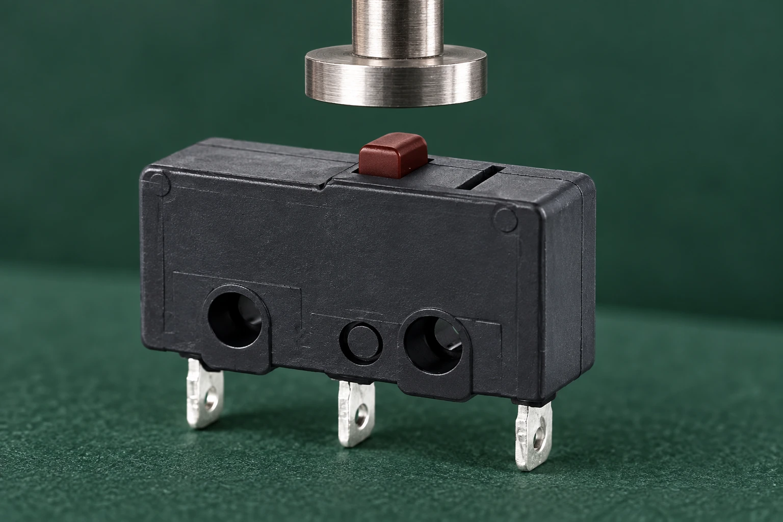
The historical NASA report on switch and circuit-breaker failure mechanisms distinguishes electrical-contact problems from mechanical problems and identifies contamination, corrosion, loose parts, wear and misalignment among potential contributors. These are general investigation categories, not failure-rate data or certifications for a modern LEMA model. Use them to organize evidence rather than to assign a cause from appearance alone.
| Reported symptom | Evidence to preserve | Investigation question |
|---|---|---|
| Required contact does not close | Isolated contact readings and actuator position. | Does movement reach the specified operating point, and is the measured circuit correct? |
| Contact remains closed after release | Free actuator position and separate electrical observation. | Is the mechanism held operated, or does the contact remain closed independently? |
| Intermittent result with repeatable movement | Repeat observations, connector condition and environmental history. | Which part of the switch-to-controller path changes while movement remains constant? |
| Switching position shifts | Bracket alignment, fastener condition and movement records. | Has the mounting or target moved relative to the switch? |
| Housing, lever or plunger is damaged | Photographs before removal and the complete actuator path. | Was unintended force or travel applied to the installed component? |
| Fault appears only during equipment operation | Load identity, operating sequence and qualified input observations. | Does the electrical duty or machine environment differ from the isolated test? |
This table requests observations before conclusions. It does not authorize dismantling an energized installation or repairing internal contacts. Establish the affected boundary before approving either a replacement or a change to the equipment.
Compare the actual load with the original approval
Retrieve the requirements used when the switch was approved: contact function, AC or DC duty, load type, switching frequency and expected service conditions. Then compare them with the real installation. A spare part carrying a similar headline current marking may have a different duty qualification. A machine modification can also change the electrical stress while leaving the switch label unchanged.
List the devices the contact actually commands or interrupts. Note whether a contactor, solenoid, electronic input or other load is connected and whether that configuration changed. If protection components exist, identify them from the wiring documentation rather than assuming an unfamiliar component provides the intended protection. Changes to suppression must be reviewed for their effects on release behavior and the wider circuit.
The general failure mechanisms in historical switch literature include contact erosion and unwanted contact adhesion associated with switching stress. These mechanisms are possible explanations, not a visual diagnosis. Confirm any proposed overload explanation against model-specific electrical evidence and a qualified examination of the returned part. Do not infer that a resistance test passing at low energy proves the load duty was appropriate.
Inspect the complete actuator movement
Check movement from the free position through operation and back to release. Inspect how the target meets the plunger or lever, whether it approaches consistently, and whether unrelated machine forces reach the switch. A component that is intended to detect position should not automatically be treated as a structural stop for the moving mechanism.
Compare the actual path with the drawing for that exact actuator variant. Record the travel after switching, mounting position and clearance through the full movement. Do not copy an overtravel allowance from another switch family. If the mechanism was adjusted, compare the current setting with the approved fixture or commissioning record before changing it again.
A repeatable shift in machine position may originate in a loose target, bent bracket or changed linkage rather than in the internal contact mechanism. Verify those external parts before selecting a different actuator. See the micro switch travel terminology guide for the relationship between operating and release movement.
Trace environmental and connection changes
Review the location as installed, including nearby spray, dust, cleaning agents, temperature changes and cable movement. The switch enclosure, exposed terminals and cable connection may have different protection requirements. A seal claim on one interface does not establish protection for every part of the assembly.
Document contamination and connector condition without assuming that all visible residue reached the contacts. Photograph displaced terminals, loose mating parts and unsupported cable runs. A damaged connector or a wire carrying mechanical load can explain an intermittent input even when the removed switch operates normally on the bench. Compare the failing position with another approved installation only when the equipment and operating conditions are comparable.
Do not spray a generic cleaner into a switch housing or scrape internal contacts as an undocumented production repair. Such actions can change materials, films and mechanical condition while removing evidence. Use the equipment manufacturer’s approved maintenance method and the component supplier’s model-specific advice.
Verify the correction instead of stopping at a new part
Write the proposed cause and the evidence that supports it. Then state what the corrective action changes. If the bracket moved, restoring the approved mounting and checking its retention addresses a different problem from changing the switch’s electrical duty. If the harness connection failed, replacing only the switch leaves the defective interface in service.
Define a test sequence that would expose the original symptom. Include operation and release, the relevant process speeds, the shortest required event and the operating condition associated with the failure. Preserve the observed result alongside the expected result. A single successful movement after replacement is weaker evidence than a repeatable sequence that reproduces the original circumstances.
Review any electrical or mechanical modification through the equipment’s approval process. For a replacement decision, use the form, fit and function replacement checklist. For purchasing requirements, the guía de selección de microinterruptores industriales helps organize the specification before sample approval.
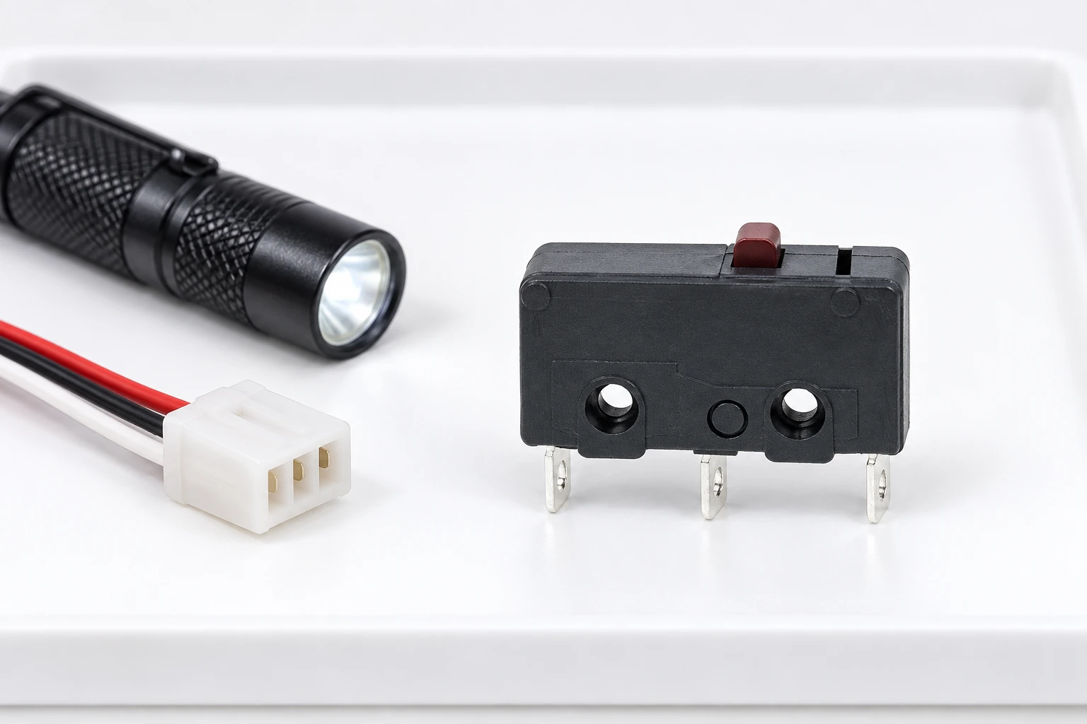
A useful LEMA return or inquiry package includes the exact part, installation photos, original and actual duty, the symptom record, isolation-test observations and proposed sample validation. The KW12 micro switch family is illustrated here as an intact external reference. The images show actuator and terminal forms; they are not photographs of failed contacts or evidence of a particular model’s service life.
Video: compare normal operation with the reported failure
RealPars explains the operating principle of a mechanical limit switch. Use this educational reference to separate external actuator movement from the contact change it is intended to produce. The principle helps frame a fault record, while the exact travel and load requirements still come from the selected model’s documents.
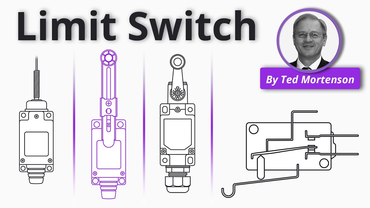
Watch the RealPars mechanical switch explanation.
Preguntas frecuentes
Does an intermittent input prove that the micro switch is faulty?
No. Preserve the symptom and check the switch, harness, mechanism and controller separately. A connection or movement problem can produce a similar input fault.
Can a continuity test rule out every failure mode?
No. It can screen contact states in an isolated circuit. It does not establish correct switching duty, environmental performance or operation throughout the machine’s movement.
Should I open or clean a failed micro switch before returning it?
Preserve its original condition and follow the supplier’s return instructions. Opening or cleaning can remove evidence and introduce damage that makes the original cause harder to assess.
Why can the same fault return after switch replacement?
The cause may remain in the load, actuator movement, mounting, environment or connection system. Validate the corrective action under the conditions associated with the original failure.