
Power socket contact resistance adds electrical loss at the mating interface. Under a given current, a higher resistance produces more local power dissipation, but resistance alone does not predict the final temperature. The contact geometry, surrounding materials, ventilation and operating conditions also matter. For an equipment inlet, evaluate the complete mated connection and the actual application. Start with an isolated, repeatable resistance measurement and a qualified thermal validation plan. Do not use a continuity beep, a cool exterior surface or an unverified catalog number as proof that the connection is suitable.
This guide concerns panel-mounted equipment power sockets and inlets, rather than household wall receptacles or RV shore-power connectors. It focuses on how to interpret contact measurements and plan a heat-rise investigation. Work involving installed mains equipment requires qualified personnel, suitable test equipment and the equipment’s documented safety procedure.
Define the connection being measured
Identify the inlet, mating connector, terminals and measurement points. The resistance between two accessible points may include the mating interface, metal within the inlet, the cable termination and part of the cable. Without a clearly stated test boundary, two apparently different contact-resistance results may simply describe different paths.
Record the exact inlet and cord-set identities, their condition and whether they are fully mated. Preserve the mounting arrangement and cable support in the test record. A new loose sample on a bench is not necessarily representative of a connection installed in a warm enclosure. Conversely, a measurement including a long cable cannot be described as the inlet’s contact resistance alone.
Il University of Maryland CALCE contact-resistance measurement overview describes evaluation using actual contact geometry and controlled environmental conditions. It supports a central practical distinction: measure the connection in a defined configuration, and retain the conditions needed to interpret or repeat the result.
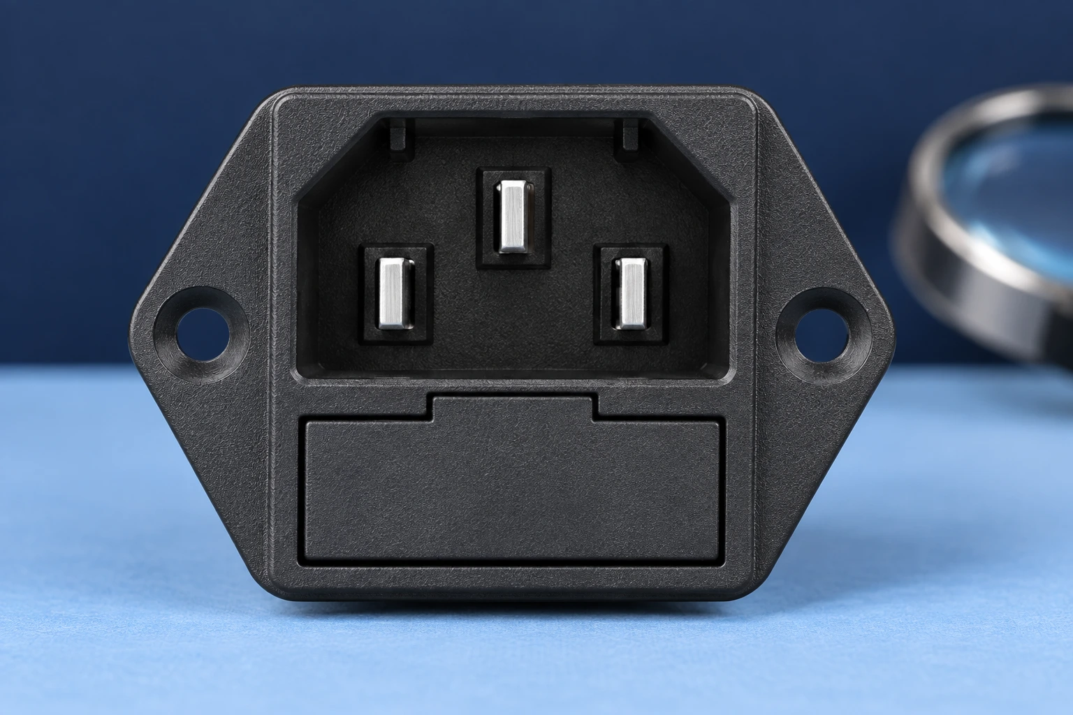
Use electrical power to understand the heating mechanism
For a resistive section carrying current, the local power loss is P = I²R, where P is watts, I is amperes and R is ohms. The University of Colorado Boulder I²R heating demonstration illustrates the relationship between current, resistance and heat generation. For an AC calculation, use the appropriate RMS current and a resistance representative of the conditions being considered.
As an arithmetic example only, assume a measured resistive path of 0.010 ohm carries 5 amperes. The calculated loss is 5 × 5 × 0.010 = 0.25 watt. At 10 amperes with that same assumed resistance, the loss becomes 1 watt. These numbers describe a hypothetical path; they are not a LEMA specification, a permissible operating current or a verified thermal result.
Keep the units explicit. Convert milliohms to ohms before using the formula. A change in the written unit can change the calculated result dramatically. If a catalog unit is ambiguous, obtain written clarification rather than choosing the interpretation that seems plausible. Record the original document and the clarified measurement condition with the approval file.
For selecting between physical connection families, see the separate C14 equipment inlet selection guide. A connector designation and a headline rating do not replace evaluation of the real mated path.
Keep power loss separate from temperature rise
A calculated watt value is not a temperature in degrees. Temperature depends on how the generated heat moves through the contact, housing, termination, panel and surrounding air. Different installations can therefore reach different temperatures with the same measured electrical loss. Resistive heating is a reason to investigate; it is not a complete thermal model.
Define where temperature will be measured and which limit applies to that location. A contact interface, a terminal, a plastic surface and an accessible panel are different measurement points. Do not transfer an acceptance criterion from one point to another without the applicable product or equipment requirements. The hottest internal region may not be visible from an exterior thermal image.
Include ambient conditions, enclosure operation, load sequence and stabilization criteria in a qualified test plan. Keep the equipment in the arrangement used for approval, including adjacent heat sources and normal cooling. The plan should identify who is authorized to run the energized test and how the assembly will be made safe before any subsequent inspection.
| Domanda | Evidence required | What the evidence does not prove |
|---|---|---|
| Is the measured resistance repeatable? | Defined points, instrument method, mating state and repeated readings. | A repeatable number alone does not establish suitability under load. |
| How much resistive power is lost? | Current and resistance with compatible units and stated conditions. | Calculated watts do not directly establish temperature rise. |
| Where does the connection become warm? | Approved temperature measurements with locations and ambient conditions. | An exterior image does not necessarily show the hottest internal contact. |
| Did service change the connection? | Comparable baseline and later results, mating history and condition records. | A changed number does not identify the cause without investigation. |
| Does the assembly pass? | Applicable equipment and exact component criteria with a documented test. | A continuity beep or one successful power-up is not thermal acceptance. |
The table is a planning aid. It deliberately avoids a universal maximum resistance or temperature limit. The applicable criteria must come from the exact approved component, connection system and equipment requirements.
Choose a resistance method that matches the question
An ordinary two-wire reading includes effects from the test leads and their connections. For a very small resistance, those contributions can obscure the part of interest. A four-wire measurement separates the current path from the voltage-sensing path, allowing a more useful assessment when the instrument and fixture are suitable. It still requires defined contact points and a repeatable setup.
For the measurement principle, the University of Illinois explanation of four-probe measurement describes why an additional sensing arrangement can reduce unwanted contributions from contacts. Applying the principle to an equipment inlet requires an appropriate fixture; a general conductivity explanation is not an inlet test standard.
Document instrument identity, range, test-current conditions, sample temperature and the way each lead is attached. Do not change the contact pressure or mating condition simply to obtain a lower number. If the fixture itself changes the connection, the result may describe the fixture rather than normal use. Confirm that the proposed measurement does not unintentionally energize other equipment paths.
A continuity function can help identify an open circuit, but it usually answers a different question from a low-resistance evaluation. Use it as a screening observation. Do not turn an audible indication into an acceptance value unless the instrument method and the equipment requirement explicitly support that interpretation.
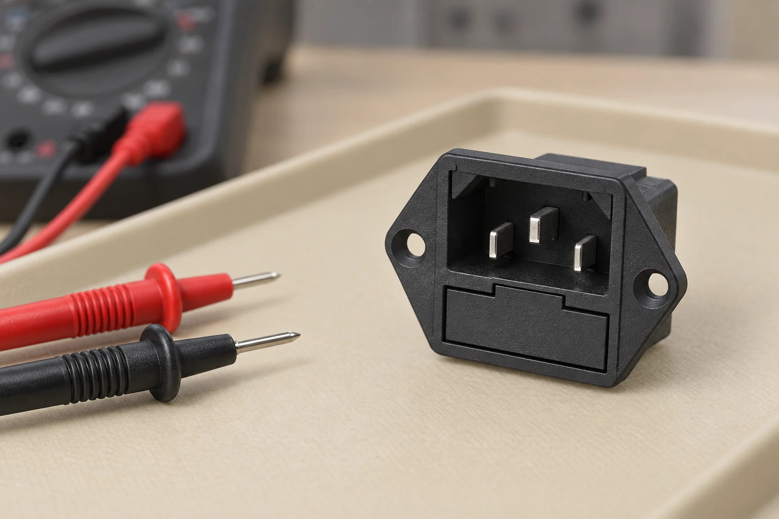
Investigate a changing value without guessing its cause
If readings change, first check whether the measurement setup changed. Review lead placement, fixture connection, instrument range and sample temperature. Then examine the defined mated connection and termination. Keep the original and repeated results rather than discarding an inconvenient value as an outlier without an explanation.
Registra la cronologia delle accoppiamenti e qualsiasi evento meccanico o ambientale associato alla modifica. Un cavo o connettore di sostituzione apparentemente simile può creare un'interfaccia diversa. Un connettore che non è completamente inserito cambia anche l'installazione. Conferma la compatibilità dai documenti approvati invece di presumere che una parte sia accettabile perché può essere inserita in posizione.
Non piegare i contatti, applicare materiale conduttivo improvvisato o forzare una parte di accoppiamento non adatta per ottenere una lettura migliore. Se si sospetta danno, surriscaldamento anomalo o instabilità, rimuovere l'apparecchiatura dal servizio secondo la procedura approvata e conservare l'assemblaggio interessato per un'indagine qualificata. Il risultato della resistenza è una prova da interpretare, non una ragione per bypassare un requisito di protezione esistente.
Approva l'assemblaggio con una linea di base tracciabile
Crea un record di approvazione collegando l'ingresso, il connettore di accoppiamento, la terminazione e la configurazione installata. Indica il metodo di resistenza, le posizioni di test termici e i criteri di accettazione. Includi il carico previsto e l'ambiente operativo. Questo rende un'indagine di servizio successiva molto più utile rispetto a un singolo numero inspiegato scritto su un sacchetto di campioni.
Rivisita il record quando il set di cavi, il formato del terminale, la disposizione del pannello o il carico operativo cambiano. Decidi quali controlli devono essere ripetuti prima della messa in servizio. Una sostituzione di acquisto che preserva le dimensioni frontali può comunque richiedere una nuova revisione dell'intera connessione. Il guida alla presa di alimentazione montata sul pannello copre le considerazioni di montaggio, mentre il C13 and C14 comparison spiega i ruoli di accoppiamento.
Per una richiesta LEMA, fornisci il requisito di connessione esatto, la parte di accoppiamento, l'ambiente installato e i criteri di test da confermare. La famiglia di prese di alimentazione dell'attrezzatura IPZ fornisce il riferimento reale del prodotto utilizzato in queste illustrazioni. Richiedi un disegno specifico del modello e unità chiarificate prima di utilizzare qualsiasi valore di resistenza in un calcolo di approvazione. Nessun valore di resistenza di catalogo o certificazione è dichiarato verificato da questo articolo.
Video: potenza elettrica e perdita resistiva
Khan Academy spiega la potenza elettrica nei circuiti resistivi. La lezione aiuta a interpretare il calcolo I²R usato qui. Non dimostra un test di qualificazione dell'ingresso né fornisce una temperatura di contatto consentita per un'assemblaggio specifico.

Guarda la lezione di Khan Academy sulla potenza elettrica.
Domande frequenti
Un segnale acustico di continuità dimostra che una presa di corrente rimarrà fresca?
No. È un'indicazione di screening, non una specifica di resistenza o un test termico. Valutare la connessione accoppiata definita secondo i requisiti dell'apparecchiatura applicabili.
Posso calcolare la temperatura di contatto direttamente da I²R?
No. I²R indica la perdita di potenza resistiva in watt. La temperatura dipende anche dal trasferimento di calore dell'installazione e dalle condizioni operative.
Perché utilizzare una misurazione a quattro fili per resistenze basse?
Separare i percorsi di rilevamento corrente e tensione può ridurre le contribuzioni indesiderate di conduttori e connessioni. La staffa, i punti di misura e le condizioni di prova devono comunque essere controllati.
Esiste un limite di resistenza di contatto per ogni ingresso dell'attrezzatura?
No. Utilizzare i criteri di componenti e attrezzature approvati esattamente, con unità chiare e condizioni di misurazione. Richiedere chiarimenti quando una voce del catalogo è ambigua.