
An industrial foot switch replacement must preserve the original command behavior, electrical interface and installation requirements. A similar pedal shape or matching plug is not enough. Record the original part and machine response, compare the candidate against the approved documentation, and validate the finished assembly before return to service. This guide covers ordinary industrial command pedals and their replacement evidence. It does not approve substitutions in emergency-stop, enabling, guarding or other protective functions, and it does not address guitar effects, sewing-machine speed controllers or household lamp foot switches.
For equipment builders and maintenance buyers, the practical question is whether a proposed substitute reproduces the complete approved function. The pedal, cable, connector and receiving input all matter. Keep that comparison separate from a catalogue search so availability does not silently override the machine requirements.
Capture the original configuration before removal
Record the full pedal order code, visible markings, cable identification, connector details and machine drawing revision. Photograph the as-installed location and routing before moving anything. Note whether the unit is loose on the floor, fixed to a support or part of a guarded station. Include any secondary command, indicator or mechanical feature that participates in normal operation.
Write down what the machine does when the operator presses and releases the pedal. Distinguish a momentary command from a maintained state and from a controller that retains a command after a short press. Observe the documented sequence rather than conducting an unsafe experiment. If the machine is already faulty, use the approved description and records; the failed behavior is not the reference that the replacement should reproduce.
Consult the industrial electric foot switch selection guide when reconstructing the initial requirements. A replacement review starts from those requirements and the actual equipment documentation, not from the fastest available item in the same product category.
Match action independently of contact arrangement
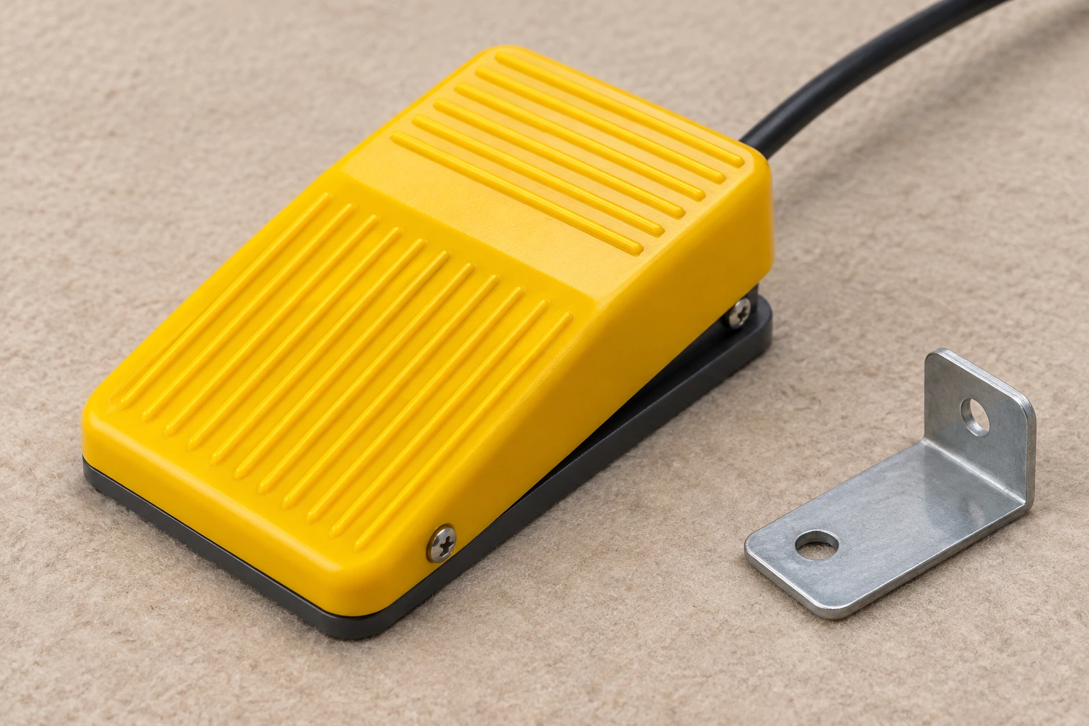
A momentary pedal normally returns when the operator releases it. A maintained mechanism retains a selected state until its specified reset or next operation. These descriptions concern mechanical action. Normally open and normally closed describe the contact state in its defined normal condition. Neither distinction alone establishes the machine’s complete command behavior.
Build a state table for the original circuit: released, operated and returned or reset. Identify which contact pairs the equipment uses in each state. Do not assume that the same number of conductors means the same contacts, or that a pedal with two outputs can replace a single-output unit without reviewing the unused paths. Verify the order-code-specific arrangement.
O maintained versus momentary foot switch comparison explains the action distinction. Also check whether the controller expects an edge, a sustained level or another documented sequence. A pedal can appear to operate normally yet deliver the wrong command timing to the receiving input.
Separate dry contacts from powered interfaces
Determine whether the original assembly presents an isolated contact, switches a defined load, or contains electronics. Some devices that look like foot switches are variable-control pedals or specialized interfaces. An ordinary contact pedal cannot automatically replace them. An illuminated or multi-function unit may also have separate supply requirements that are not visible from the housing.
Use the schematic to identify the receiving circuit and electrical duty. A current rating printed for one voltage or load type does not establish suitability for another. Do not equate a mains load rating with reliable performance at a small control-input current, or infer a DC switching rating from an AC marking. Request the specific contact-duty information needed for the equipment.
Where the original pedal participates in a protective function, stop the ordinary substitution process. The machine designer’s approved safety architecture and validation requirements govern that decision. This article provides no basis to replace a protective arrangement with a general command pedal, remove a guard or bypass an interlock to keep a machine operating.
Use a replacement comparison table
The table is a comparison format, not a list of universal acceptance values. Attach drawing references and documented results for the original and candidate. An unresolved difference is a review item. Do not mark the complete replacement accepted while a relevant field remains unsupported.
| Requirement | Compare on both assemblies | Why appearance is insufficient |
|---|---|---|
| Ação | Pressed, released and reset behavior | The controller may retain a command independently |
| Contact function | Used contact pairs and state table | Conductor count does not establish contact topology |
| Dever elétrico | Load type, voltage, current and input requirements | A rating for another duty does not approve this circuit |
| Cabo e conector | Pin assignment, route and strain relief | A plug can fit while its internal assignment differs |
| Instalação | Foot access, mounting and unintended-operation controls | A different profile can change reach or accidental actuation |
| Verificação | Approved sequence and recorded machine response | One successful press does not demonstrate the complete sequence |
Keep the comparison linked to a specific candidate order code. A family description may cover different contact configurations or cable options. The approved configuration should identify the chosen variant, documentation revision and any customization. This prevents a later purchase from substituting a different family member under the same general name.
Review the complete cable and connector path
Measure the required routing path and service allowance within the equipment design. Check whether the candidate’s cable reaches without tension, tight bends or exposure to moving parts. Do not add a splice simply to solve a length mismatch without an approved termination and protection method. Compare the intended conductor construction and environmental suitability through the relevant specification.
Inspect strain relief at the pedal and receiving connection. The load path should not pull on the internal termination during normal repositioning or service. A replacement cable may be stiffer or enter the housing differently, changing the bend and tension at a station. Verify the installed result rather than judging the cable while it is coiled on a bench.
For connector-equipped assemblies, obtain the pin assignment, keying details and mating-part specification. Check from the documented view direction. The foot switch cable and strain-relief guide supports routing decisions, but the replacement still needs its own point-to-point record and the machine’s approved connection instruction.
Preserve operator access and installation safeguards
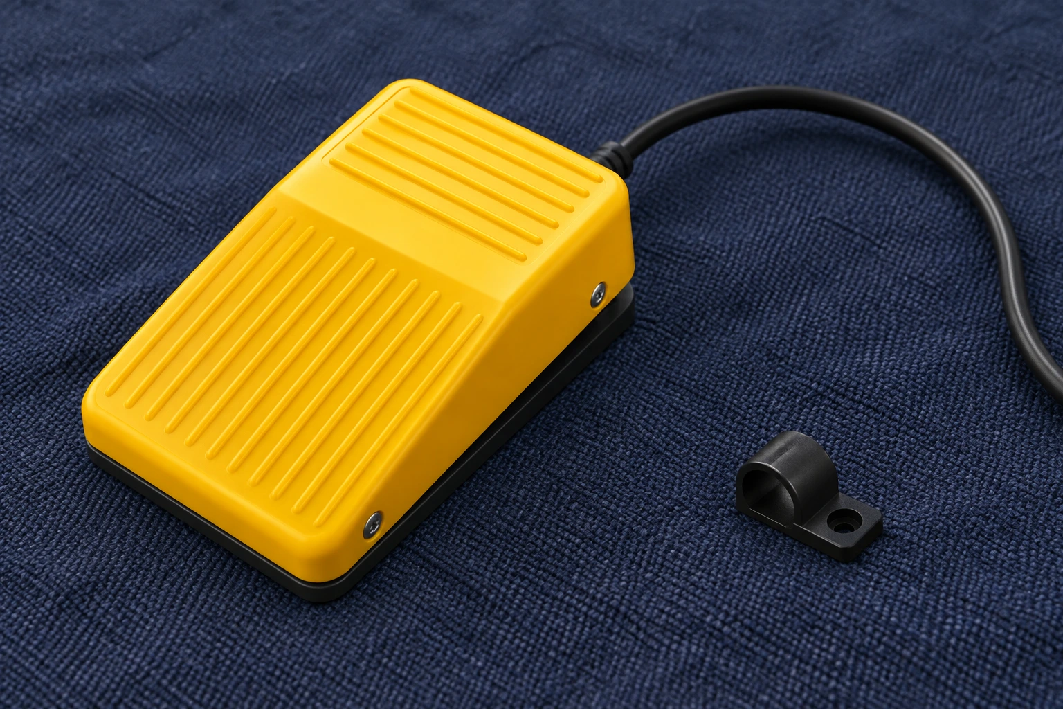
Compare pedal height, contact area, action feel and placement with the original station. A substitute that is harder to reach or slides during operation can change how operators use the equipment. Evaluate the assembled station with the relevant users and machine requirements. Do not invent an acceptable operating force from a photograph or use comfort alone to approve a protective function.
Retain required guards, supports and controls against unintended operation. Check whether the replacement changes the relationship between the pedal and an existing protective cover. If the original installation uses specific mounting holes or anti-slip provisions, verify the candidate against those details. Do not remove an enclosure or enlarge openings without the appropriate equipment review.
Environmental claims must be order-code-specific. A statement that a pedal is industrial does not establish sealing under washdown, chemical exposure or cable flexing. Request relevant evidence and confirm the installation maintains the intended protection. Inspect covers and cable entries after assembly, especially where the replacement required a different route or termination.
Isolate, install and test under the approved procedure
Follow the equipment’s servicing and hazardous-energy procedure before removal or installation. Electrical energy may not be the only source; account for stored, pneumatic, hydraulic or mechanical energy where relevant. The United States regulation on control of hazardous energy provides an authoritative reference for covered workplace servicing. A pedal release or controller stop command is not an energy isolator.
After safe isolation has been established, competent personnel can use approved contact and connection checks to compare the assembly with its state table. Disconnect enough of the circuit to avoid misleading parallel paths. Record the instrument and method. The isolated foot switch testing guide explains supporting measurements and their limits; a continuity indication alone does not establish load capability or complete equipment safety.
HSE’s electrical testing safety guidance provides background for managing testing risk. Return-to-service checks must follow the equipment’s approved sequence. Verify the command, release, reset and required fault response under controlled conditions. Do not bypass another device to make the new pedal appear functional.
Send a complete replacement enquiry and retain evidence
When considering the LEMA LF series foot switch family, provide original part information, required action, the contact-state table, electrical duty, cable route, connector assignment and installation photographs. Ask which exact variant matches the documented requirements. The family reference does not establish that every LF pedal can replace every industrial control.
Record every difference and its accepted resolution before ordering production quantities. Where documentation is incomplete, request a sample and a defined verification plan. Retain the approved sample, drawing, test results and supplier correspondence together. Later incoming checks should compare the delivered assembly with that reference rather than only checking colour and packaging.
A replacement is complete when its documented function and installed response match the approved requirements. Keep the old failure evidence if an investigation remains open. Replacing a pedal may restore operation while leaving the original cause, such as cable stress or unsuitable duty, unresolved. Close that cause separately so the new assembly is not exposed to the same preventable failure.
Further learning
This independent educational video provides background for the checks discussed above. It does not identify the terminals of the illustrated LEMA product or replace the equipment manufacturer’s approved procedure.

Watch How to Test PLC Digital Inputs and Outputs (Step-by-Step Guide) — RealPars
Perguntas frequentes
Can a matching plug prove a foot switch is interchangeable?
No. Check its pin assignment, contact function, action, electrical duty and the receiving equipment interface against the approved documentation.
Can I replace a speed-control pedal with a contact foot switch?
Not without a design review. A variable-control or electronic pedal may present a different interface from an ordinary contact switch.
Does continuity approve a replacement for its load?
No. Continuity helps verify isolated connection states; it does not establish load duty, endurance, sealing or complete equipment safety.
Can this guide approve a safety foot switch substitution?
No. Protective functions require the machine designer’s approved components, architecture and validation procedure.