
A micro switch for a mouse button must match the complete input assembly: the PCB footprint, terminal function, plunger position, button-shell travel and low-current sensing circuit. A switch that physically enters the holes is not automatically an approved replacement. For an OEM design, evaluate the switch together with the shell and firmware; for a repair, compare the exact original part and verify the assembled result. This guide focuses on mechanical contact switches, using LEMA’s KW10-0P as a product-reference example without claiming compatibility with any named mouse or assigning unverified lifetime figures.
Identify the input technology before comparing parts
Start by determining whether the mouse uses a mechanical contact switch, an optical sensing arrangement or another button mechanism. A mechanical microswitch changes an electrical contact state when its plunger moves. An optical button uses a different sensing path. Similar external button shapes do not make these technologies interchangeable, and a mechanical switch should not be offered as a universal replacement for an optical assembly.
Within mechanical designs, record the manufacturer’s part marking and the board position. Left and right buttons may use similar switches, while a wheel button or side button can have another package or actuation direction. Photograph the component, its orientation and the surrounding structure before removing anything. Keep the PCB revision in the record because a model name alone may cover several hardware revisions.
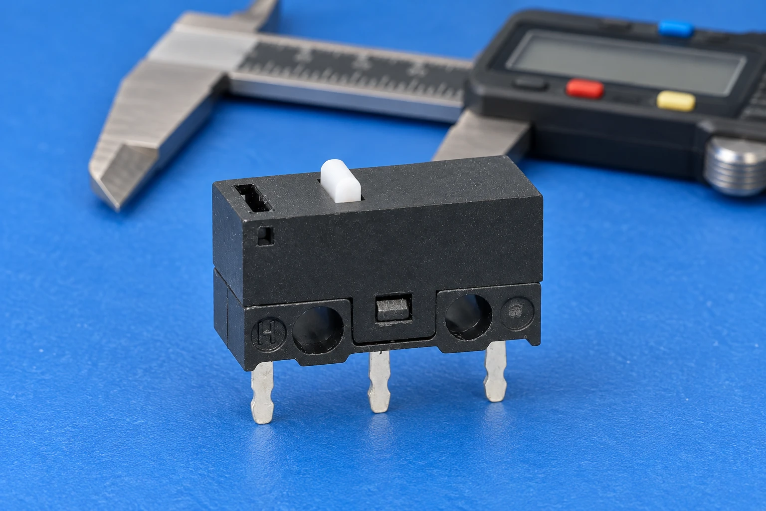
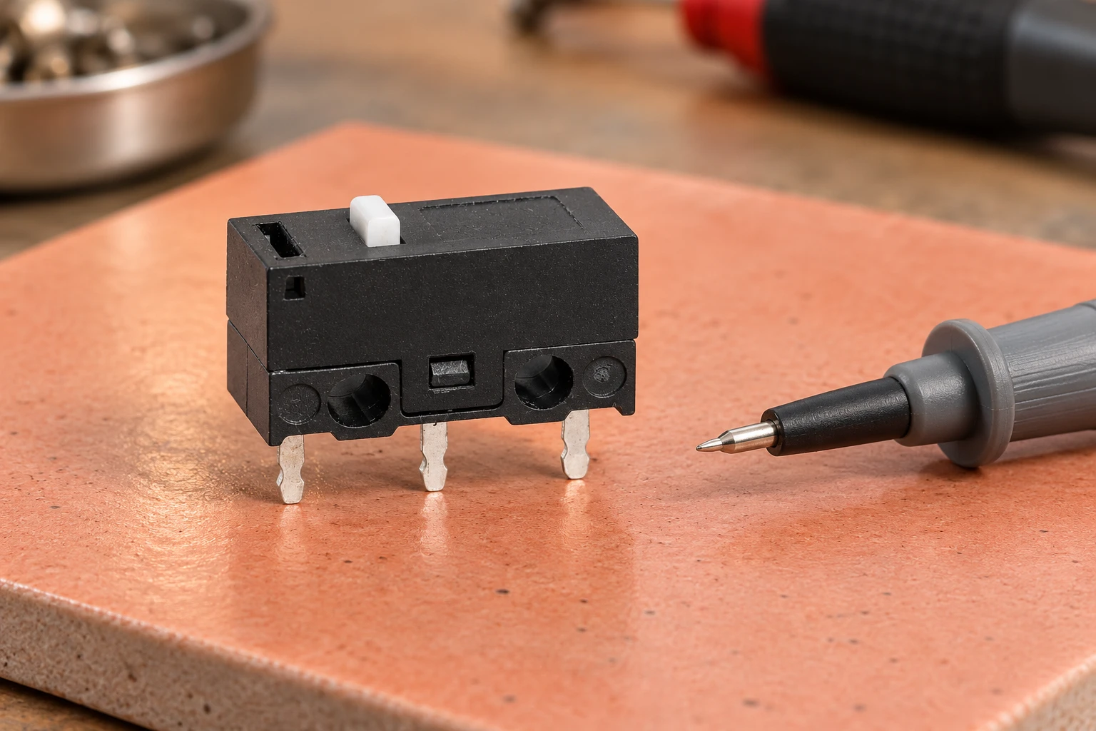
O Página do produto LEMA KW10-0P provides a real compact PCB-terminal microswitch reference. Its black housing, white plunger and three visible pins are useful for a form comparison. They do not establish the terminal sequence, a particular mouse’s compatibility or the operating force of every orderable variant. Request the drawing and specification for the complete purchasing code.
Match the footprint and terminal function separately
Compare pin spacing, pin thickness, hole locations, housing outline and plunger location against the actual board drawing. Three pins arranged in a line can appear familiar while differing in their position or required pad clearance. A slight housing change can collide with a rib inside the upper shell, and a change in plunger height can preload the switch after assembly. Check the installed envelope rather than comparing only the loose parts.
Identify the contact functions from the exact manufacturer’s diagram. A changeover switch can offer common, normally open and normally closed connections, but the physical order of those connections must come from verified documentation or an isolated state measurement. Do not infer the common terminal from its location or assume the board uses every pin. Some pads provide mechanical support while a circuit uses only the contact path it needs.
Use the site’s isolated microswitch testing guide for the measurement procedure and its limitations. A continuity test can identify released and pressed states on a disconnected component. It does not validate low-current reliability, firmware timing or long-term performance. Keep the pin-function result distinct from the complete product approval.
Evaluate force and travel in the assembled button
The user’s finger acts on a molded button shell, not directly on the switch plunger. That shell has its own hinge, stiffness, leverage and mechanical stops. A switch with the same nominal operating force can feel different when installed under another shell. Conversely, a force difference that seems small on the bench may change the assembled button’s feel or its ability to release consistently.
Measure the released clearance, the movement needed to operate the switch and the additional movement allowed by the shell. The shell should not hold the plunger partly operated at rest. Its travel should operate the switch reliably while staying within the supplier’s permissible overtravel. Do not rely on the switch housing as an unapproved hard stop or apply a generic travel limit to every package.
Compare the left and right button assemblies with the same measurement fixture and method. Record where the force is applied, because pushing near the front edge can produce a different result from pushing near the hinge. Repeat slow presses and normal use rather than judging a single click. The pretravel, overtravel and differential travel explanation helps separate these measurements without confusing shell movement with internal contact travel.
A practical OEM comparison record
| Campo de decisão | Provas a recolher | Acceptance question |
|---|---|---|
| Input technology | Board schematic and original component identity | Does this assembly actually use mechanical contacts? |
| Footprint and envelope | Exact variant drawing plus board and shell comparison | Do pins, pads, plunger and surrounding ribs align? |
| Contact function | Manufacturer terminal diagram and isolated state record | Does the required released/pressed path match the circuit? |
| Force and travel | Specified operating range and assembled button measurements | Does the shell operate and release without excess movement? |
| Low-level electrical duty | Actual sensing voltage/current and supplier suitability evidence | Is contact performance supported at this circuit’s duty? |
| Input timing | Captured contact waveform and firmware configuration | Are intended presses recognized without duplicate events? |
| Production controls | Approved code, revision, lot identification and sample record | Can the tested assembly be reproduced in production? |
This qualitative checklist deliberately contains no universal force, dimension or endurance requirement. Agree the limits with the equipment design owner and switch supplier. Consumer reviews and colored housing marks can help identify candidate parts, but neither replaces the ordered variant’s drawing, electrical conditions and qualification record.
Low-current sensing needs its own evidence
A mouse button commonly feeds an input circuit rather than switching a large appliance load. Ask the design owner for the actual voltage, current, pull-up arrangement and input thresholds. A high maximum current printed on a switch is not proof of dependable operation at a much smaller sensing current. Contact material, contamination, surface condition and the specified test method matter to low-level performance.
Separate mechanical life from electrical life and assembled-device endurance. A supplier’s mechanical cycling result may use different conditions from the actual PCB circuit. Record the load, actuation speed, environment and failure criteria behind any claimed endurance. Do not promise a mouse service life by transferring a family-level cycle figure or an unrelated competitor’s specification to the selected LEMA part.
For additional OEM evidence planning, the electrical versus mechanical life guide explains why those figures answer different questions. Qualification should follow the device’s actual operating conditions. Buyers should ask for suitable contact-duty evidence and agreed sample validation instead of ranking parts solely by the largest advertised number.
Distinguish bounce from a complete double-click diagnosis
A mechanical contact can produce several transitions during one operation before it settles. Firmware may filter those transitions, but the required timing depends on the captured signal and application response requirements. Jack Ganssle’s measured switch-bounce study illustrates why a single assumed bounce duration is a poor substitute for measurements. Its tested switches are educational examples, not qualification data for the illustrated KW10 product.
A reported double click can also involve worn mechanics, unstable contact resistance, a loose solder joint, shell preload or software behavior. Replacing a switch without finding the cause can leave the fault unchanged. Compare physical motion, the electrical signal at the circuit and the events reported by the host. Preserve the test configuration so another technician can reproduce the result.
For a new design, capture both press and release behavior across representative samples. Confirm that firmware handles short unintended transitions while recognizing the intended press and release. Avoid recommending an arbitrary debounce setting as universal. If a repair needs an unexplained software delay to appear stable, treat that as a diagnostic clue rather than proof that the new hardware is acceptable.
Control handling, soldering and final acceptance
Disconnect the device and follow its repair procedure before working on the board. Use appropriate electrostatic-discharge controls for exposed electronics; the NASA’s dated ESD handbook overview explains the role of protected work areas and operator training. Use it as background, together with the current device repair procedure. A loose component inspection photo is not an instruction to apply heat or test an energized board.
Follow the switch and PCB manufacturers’ soldering instructions. Excessive heating, repeated desoldering or mechanical force can damage the housing, pads and through-hole plating. Do not invent a soldering temperature or duration for a part without its process specification. After the approved operation, inspect the joints and board condition before evaluating the assembled button.
Close the shell and repeat the agreed functional checks. Verify released state, consistent pressing, release response and neighboring-button behavior. Compare the actual output events with the physical action and record any abnormal motion or contact behavior. An open-board test misses shell preload and clearance defects that appear only after fastening the enclosure.
Build a purchasing request that can be checked
Send the supplier the original part identity, board drawing, installed envelope, plunger requirement, contact function and actual low-level duty. Include assembled force/travel targets, process requirements, sample quantities and acceptance tests. Ask the supplier to identify the exact orderable variant and its drawing revision. Do not ask for a vaguely described gaming switch and assume appearance establishes equivalence.
Keep the approved sample and its records with the production purchasing code. If the supplier proposes a substitution, repeat the affected checks before approval. LEMA can be contacted through the product inquiry path for model-specific evidence; this article does not assert that every available KW10 variant fits a particular consumer device. A useful inquiry defines the interface and validation needs clearly enough for both parties to verify the proposal.
Further learning
This independent educational video provides background for the checks discussed above. It does not identify the terminals of the illustrated LEMA product or replace the equipment manufacturer’s approved procedure.
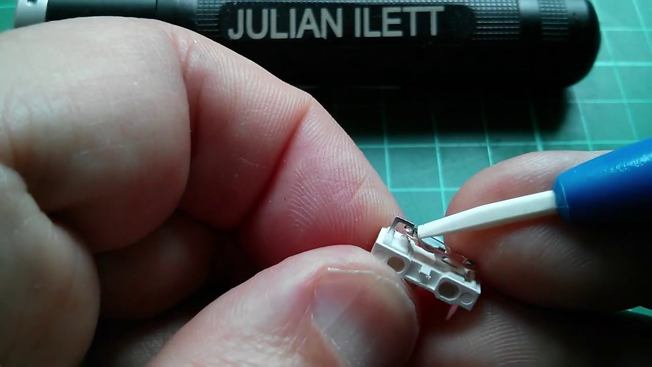
Watch What’s Inside a Microswitch — Julian Ilett
Perguntas frequentes
Are all three-pin mouse microswitches interchangeable?
No. Match the footprint, contact functions, plunger height, force, travel, shell clearance and electrical duty for the exact assembly. A similar pin count does not prove compatibility.
Does a higher advertised cycle count guarantee a longer-lasting mouse?
No. The test conditions, electrical duty, mechanics and failure criteria must match the application closely enough to support the claim. Family-level figures are not universal device-life guarantees.
Can a mechanical microswitch replace an optical mouse button?
Not as a direct assumption. The sensing technology and supporting circuit differ. Any redesign needs the device manufacturer’s electrical and mechanical approval.
What should an OEM send when asking about a mouse-button switch?
Provide the board and shell interface, exact original identity, contact function, sensing conditions, force and travel targets, process requirements and sample acceptance plan. Ask for a complete variant code and drawing revision.