
Equipment power inlet replacement requires more than finding a connector that accepts the existing cord. Match the original inlet family, mounting arrangement, approved electrical duty, terminations and protective-earth path, then validate the repaired assembly using the equipment manufacturer’s procedure. A physically compatible C14 inlet can still be unsuitable because of different panel retention, rear clearance, contact temperature or approval conditions. Begin with the equipment model and service documentation, not a marketplace photograph. This guide explains how an OEM buyer or qualified maintenance team can document a replacement decision without assuming that every black three-contact inlet is interchangeable.
Define the replacement boundary before buying
Identify whether the failed part is a plain inlet, a combined inlet and fuse holder, or a complete power entry module with switching or filtering. These assemblies may look similar from the front while performing different functions behind the panel. Replacing a complete module with a plain inlet would remove parts of the original circuit and requires an engineering redesign rather than a routine component substitution.
Record the equipment manufacturer, model, serial number and original component identification. Obtain the service manual or approved bill of materials when available. If markings are unreadable, do not reverse engineer a current rating from dimensions or contact thickness. Request identification assistance with clear photographs, the panel drawing and the circuit documentation. A damaged part can help identify its geometry, but it does not establish acceptable replacement performance.
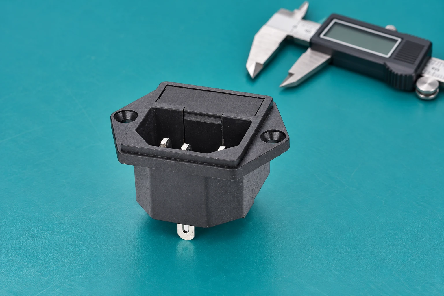
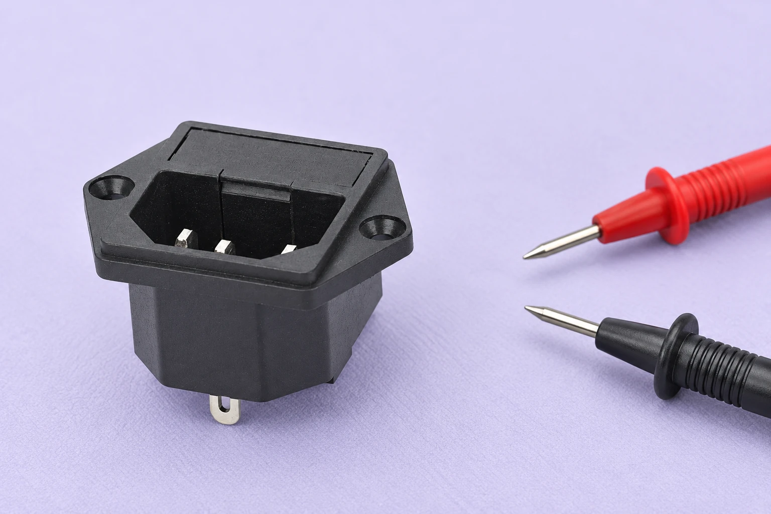
O LEMA IPZ product family provides an example of equipment inlet construction. The illustrations here are based on the site’s screw-mounted product photograph. They show physical features only; they do not certify an installation, identify conductor positions or establish the illustrated variant’s current, temperature or regional approval.
Separate component failure from equipment failure
A loose cord, discoloured housing or intermittent supply does not prove that the inlet alone caused the problem. Damage may begin at a worn cord connector, poorly retained terminal, unsupported cable, overload or nearby heat source. Record the symptoms before removal so the replacement does not conceal an unresolved fault. Retain the original part for examination and keep it clearly separated from approved spares.
Look for evidence such as mechanical movement at the panel, fractured retention features, visible contact damage or heat effects. Inspection occurs only after the equipment has been placed in a safe isolated condition. Qualified personnel should determine whether damage extends to the cord connector, wiring, enclosure or other components. If an inlet and its mating connector are both damaged, approving only one new part may leave the original fault path in place.
For a wider diagnostic framework, see equipment power socket failure modes. That article identifies possible fault paths; this replacement guide focuses on documenting the proposed substitute and accepting the completed repair.
Build a comparison record for the exact substitute
Use manufacturer drawings and approval documentation to compare the original and candidate. The IEC catalogue identifies IEC 60320-1 as the general requirements standard for appliance couplers. Refer to the applicable standard sheets and the equipment’s approved specification to establish the connector family. The standard’s name by itself is not evidence that a particular supplied component has been evaluated.
| Comparison item | Evidence to obtain | Reason to stop substitution |
|---|---|---|
| Coupler identity | Original and proposed part drawings and family designation | The mating family or contact arrangement differs |
| Dever elétrico | Exact model ratings and applicable approval conditions | Only a generic catalogue or untraceable marketplace rating is available |
| Montagem | Finished panel drawing, thickness and retention requirements | The flange, snap features or fastening method does not match |
| Rear terminations | Terminal drawing, approved mating connector and wire specification | Existing terminals require an undocumented adaptation |
| Thermal conditions | Permitted temperature conditions and equipment assessment | Candidate limits do not cover the actual installation |
| Terra de proteção | Approved circuit and protective bonding verification procedure | The earth connection cannot be positively identified and validated |
| Entry module functions | Circuit drawing and module bill of materials | Fuse, switch or filter functions would be changed or removed |
This is a qualitative acceptance record, not a table of universal ratings. Each acceptance limit must come from the exact component documentation and equipment requirements. Keep the evidence reference beside each decision rather than recording a bare tick that cannot later be audited.
Verify mounting and rear space without changing the panel
Compare the flange dimensions, hole centres, cutout shape and panel thickness with the drawing for the proposed inlet. Screw mounting and snap-in retention are different installation arrangements. A component that can be pushed into an opening may still have inadequate retention. Enlarging the opening or removing retention features changes the installation and should not be treated as a harmless adjustment.
Inspect the finished panel, including coating, burrs and distortion. The effective mounting thickness may differ from the nominal sheet thickness. Check that the component seats as intended and that approved fasteners do not interfere with the enclosure or internal wiring. Do not infer screw torque from the appearance of the flange; use the specified installation procedure.
Rear clearance must accommodate the inlet body, terminations, insulation and wire routing. A deeper substitute can bring conductors close to another component or prevent a cover from closing correctly. Use the IEC inlet cutout verification guide for dimensional records, then assess clearance in the actual enclosure rather than on a bare panel sample.
Preserve the approved termination and earth arrangement
Photographs taken before removal are useful records, but they do not replace the circuit drawing. Front and rear views can reverse the apparent left and right positions. Identify each conductor using the approved diagram and component markings, with verification performed by qualified personnel. Never assign live, neutral or earth solely from the orientation of a generated illustration or an online wiring diagram for another model.
Check the terminal size and style, the specified mating termination, conductor preparation and any insulation accessories. A replacement with different tabs may require different mating terminals. Forcing an existing connector onto an unsuitable tab, reducing conductor strands or adding an improvised adaptor can create a weak connection. The correct response is to resolve compatibility with the equipment manufacturer or responsible engineer.
Protective bonding deserves a separate acceptance item. A continuity indication is useful for identifying an isolated path, but a basic meter beep does not establish compliance with the equipment’s protective bonding requirements. Consult equipment inlet grounding checks for the distinction between identifying a conductor and validating the complete protective path.
Control removal and installation as a repair procedure
Inlet replacement involves equipment supplied from potentially hazardous electrical energy. This article does not provide a live working method. The responsible maintenance team should follow the equipment manufacturer’s servicing instructions and applicable isolation procedure, including stored energy and any additional supply sources. Disconnecting the cord alone is not a universal proof that every internal circuit is safe.
The official 2025 edition of 29 CFR 1910.147 describes control of hazardous energy for covered servicing and maintenance. Its scope and exceptions matter; cite it as a source for an appropriate workplace energy-control framework, not as a product approval or a substitute for the equipment-specific instructions.
After safe isolation is established, record the original mounting and termination arrangement before disturbing it. Protect adjacent wiring and components during removal. Install only the approved replacement and specified accessories. If the original fastening, insulation or conductor condition cannot be restored according to the procedure, stop and escalate the discrepancy instead of inventing a workshop fix.
Accept the assembly, not just the new component
Use the manufacturer’s post-service inspection and test plan. Acceptance may involve mechanical retention, conductor identification, protective bonding, insulation and functional checks appropriate to that equipment. The required methods and limits vary with equipment construction and applicable standards; do not import a numerical limit from an unrelated appliance or assume that a successful power-on proves safety.
Inspect the closed assembly for trapped conductors, missing insulation, loose hardware and altered routing. Confirm that the cord engages correctly without using the cord as a retention test beyond the approved procedure. Document any measured results together with the method, instrument identification and acceptance criteria. A recorded value without its test conditions cannot reliably support a release decision.
Where thermal damage prompted the repair, verify that the original cause has been addressed before returning the equipment to use. Qualified testing should follow the approved operating conditions and enclosure arrangement. An open bench arrangement can have different temperatures from the closed product. Do not describe an unverified no-load observation as an endurance or thermal qualification.
Send suppliers an evidence-based replacement request
A useful enquiry includes equipment identification, the original part number, drawings or measured mounting constraints, mating cord connector, required approval market and known installation conditions. Add photographs of the isolated original part and its terminations. State whether the request concerns a plain inlet or a complete module. This allows the supplier to identify questions before a sample is shipped.
Ask for the proposed exact model designation, controlled drawing, rating documentation, installation instructions and available approval evidence. Request confirmation of what differs from the original. Keep engineering acceptance separate from commercial availability: a stocked component is not automatically a validated substitute, and a family-level photograph does not establish the construction of every variant.
For repeat OEM repairs or production changes, approve a representative sample against the comparison record and preserve the accepted configuration. Record who authorised the substitution, the component revision, test results and equipment affected. Contact LEMA with the documented inlet requirements when evaluating a component supply option; final equipment compatibility and repair acceptance remain specific to the application.
Further learning
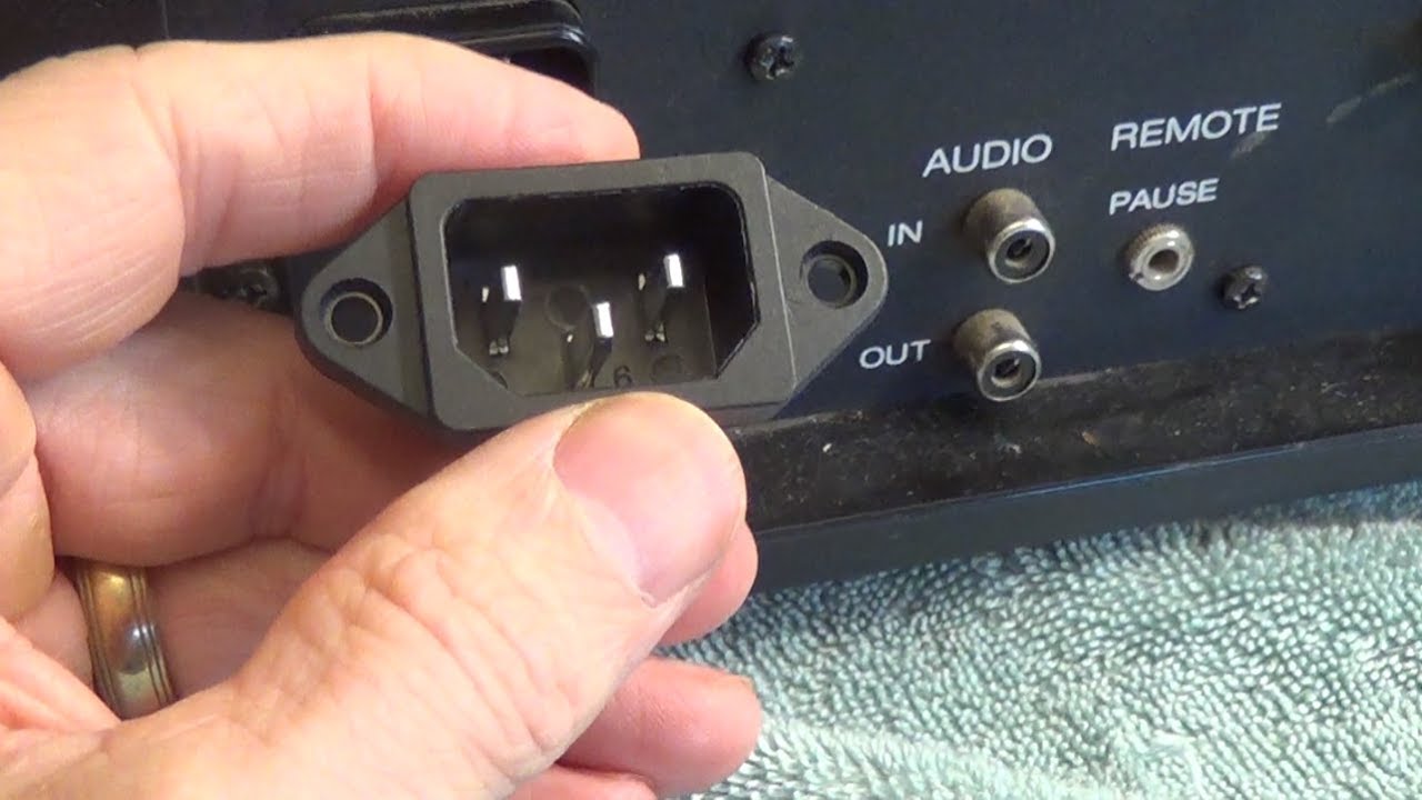
This independent educational video provides background for the checks discussed above. It does not identify the terminals of the illustrated LEMA product or replace the equipment manufacturer’s approved procedure.
Watch How to Replace an Inlet Power Plug Socket – JVC Vidstar — HowToWith GEO
Perguntas frequentes
Can I replace an inlet with any C14 part that fits the cord?
No. Mating compatibility is only one check. Compare the exact electrical duty, approval conditions, mounting, terminations, thermal requirements and complete equipment installation before approving a substitute.
Can I replace a snap-in inlet with a screw-mounted model?
That changes the retention arrangement and can require a different panel. Obtain an approved drawing and installation assessment rather than treating the two mounting types as interchangeable.
Does a continuity beep approve the repaired inlet?
No. A simple continuity check can help identify an isolated path. The repaired equipment must pass its specified inspection and test procedure, including applicable protective bonding and insulation checks.
What should I do if the original inlet markings are unreadable?
Use equipment identification, service documentation and controlled drawings to request assistance. Preserve photographs and the damaged part. Do not guess ratings from contact size, housing colour or a visually similar online listing.