
Micro switch lever edge burr inspection should identify the exact lever version, locate the questioned edge, and compare the observation with a drawing-defined acceptance requirement. A bright reflection, a rough-looking photograph, or an electrical click cannot establish whether a stamped lever edge is acceptable. Record the condition without bending or filing the lever, use a repeatable visual method, and ask the supplier for a disposition linked to the ordered assembly. This guide gives equipment buyers a practical way to distinguish an edge-condition question from operating travel, pivot clearance, and electrical performance.
Start with the correct lever assembly
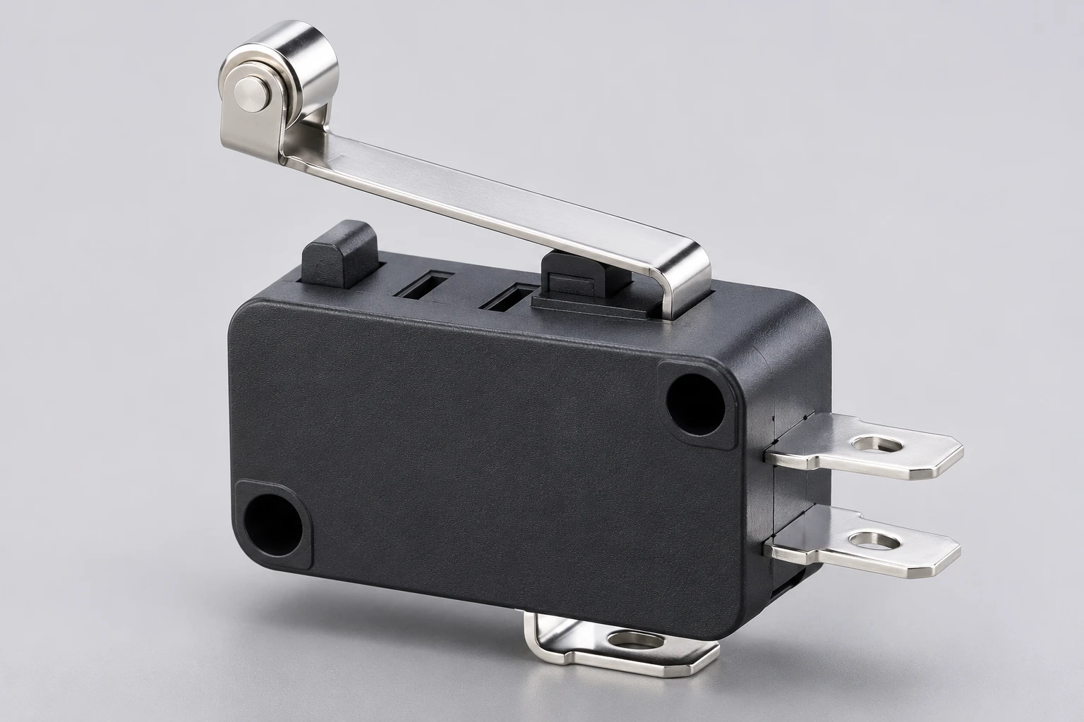
A micro switch family may include a basic plunger and multiple lever arrangements. The Lemaele KW7 series micro switch page describes lever options and shows more than one configuration. Before evaluating a lever edge, match the purchase order, part designation, drawing revision, actuator arrangement, and terminal version. A basic plunger sample cannot serve as the visual acceptance reference for a roller-lever assembly.
Do not infer the lever alloy, thickness, heat treatment, coating, or allowable burr height from its appearance. Even when two levers look alike, their ordered configuration and contact geometry can differ. Photograph the whole switch first, then the lever and the particular edge. This establishes which component the close-up belongs to and avoids sending a supplier an isolated image with no orientation.
Distinguish an unwanted projection from a specified edge
A burr is an unwanted projection at an edge; a deliberately specified chamfer, radius, or formed feature is part of the intended geometry. Removing an apparent projection does not establish that the remaining edge meets the drawing. Equally, a visibly sharp boundary is not automatically an unauthorized burr. The inspection decision needs a definition of the required condition at that location.
O DIN listing for EN ISO 13715 identifies the standard’s subject as indication and dimensioning of edges of undefined shape. Use the governing drawing and applicable standard text for actual symbols and requirements. The public listing does not supply a default KW7 lever acceptance limit. The following checklist is a proposed inspection record, not a substitute drawing.
| Evidence item | O que verificar | Decision supported |
|---|---|---|
| Identidade da montagem | Part, lever arrangement and drawing revision | Use the correct comparison sample |
| Inspection zone | Specific edge and its intended function | Apply a relevant requirement |
| Visual method | Lighting, viewing direction and magnification | Distinguish a projection from reflection |
| Measurement evidence | Defined viewing plane and calibrated method | Avoid dimensions inferred from photographs |
| Disposition | Lot, authorization and closure record | Preserve traceability through release |
Divide the lever into functional inspection zones
Ask the drawing owner to identify the edge zones that matter to the assembly. Possible areas to discuss include the actuator-contact region, a roller-support region where fitted, a mounting or pivot feature, and exposed side edges. These descriptions organize questions; they do not establish the internal construction of every KW7 option. Confirm the features on the actual ordered version before creating an inspection sheet.
For each defined zone, record why its condition matters: contact with the machine actuator, clearance to an adjacent part, handling, or another stated function. An edge close to a moving interface may require a different review from an exterior edge that never contacts another component. Avoid assigning a single universal edge rule to every surface without engineering agreement.
Set visual conditions that another inspector can repeat
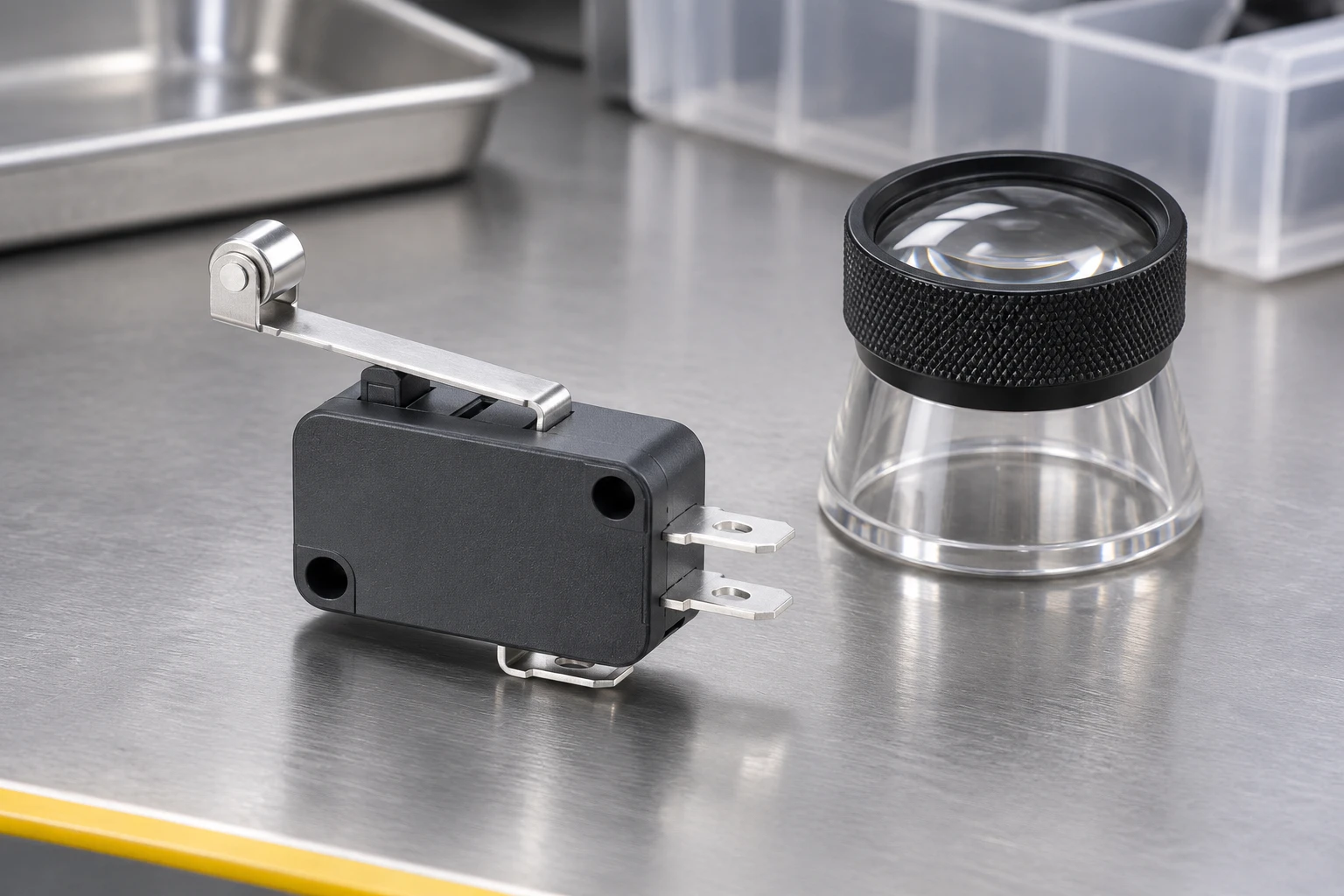
Inspect an unpowered switch on a stable support using a method that protects its lever and terminals. Record the viewing direction, illumination, magnification where used, and reference condition. Rotate the view or lighting enough to distinguish a reflection from a persistent projection. Preserve the received condition and follow supplier-approved handling and cleaning instructions rather than improvising a solvent wipe.
An image should show the edge in context and preserve its original file. If measurements are made from an image, the method needs appropriate calibration and a defined viewing plane; a ruler placed elsewhere in the scene does not automatically establish the scale of the edge. If the method cannot resolve the acceptance condition reliably, escalate the measurement instead of reporting a guessed dimension.
Use optical evidence within its actual scope
Research from Politecnico di Milano on in-line burr inspection using backlight vision describes a system developed for holes in precision turned components. It demonstrates that illumination, optics, part orientation, and the inspected geometry belong to a detection method. It does not validate the same arrangement for a switch lever, and its results cannot be transferred as a KW7 burr limit.
For procurement, request the supplier’s inspection method and representative images for the specified lever edge. Ask what feature is visible, which directions are covered, and what remains hidden. A report saying inspected under magnification should identify the relevant setup and acceptance basis. High magnification alone does not solve an unclear edge definition, insufficient contrast, or a view that conceals the feature.
Keep edge condition separate from lever operation
A lever can produce an audible click while a separate mechanical concern remains unresolved. Conversely, an operating symptom can arise from alignment, travel, mounting, or pivot conditions without being caused by a burr. Document any functional symptom alongside the edge observation, but do not claim a causal connection unless an investigation establishes it. Test the ordered assembly only under its approved conditions.
Utilize lever pivot play inspection guide for a clearance question and the mounting hole position guide for drawing-based mounting alignment. The terminal coplanarity guide covers another distinct interface. Keeping these records separate helps a supplier identify the actual cause rather than repeatedly checking the electrical contacts.
Avoid turning inspection into unapproved rework
Do not rub a bare finger along a suspected sharp edge, bend the lever, or use a file to see whether a symptom improves. Those actions can create injury risk, alter the edge, introduce particles, or change the assembly. Preserve the original sample and obtain the manufacturer’s disposition. A component that has been modified without authorization is poor evidence for judging the delivered condition.
If controlled rework is approved, it needs an explicit instruction covering the permitted operation, protection of the assembly, cleaning, and the checks needed afterward. Record which units were reworked and who authorized release. Do not assume that a general deburring process used on loose metal parts is suitable for a finished switch with a spring mechanism, contacts, and inaccessible internal spaces.
Write a useful nonconformance report
Include the order reference, exact part designation, drawing revision, lot identity, delivery quantity, inspected quantity, and affected sample identities. Mark the edge location on a copy of the overview image and preserve the original. State the observed condition in neutral language: for example, a persistent projection visible from a specified direction. Distinguish that observation from any measured value and from a proposed cause.
Then cite the requirement that appears unmet, or explicitly ask the drawing owner to clarify acceptance when no requirement is available. Request a supplier response addressing the identified edge and sample. A generic statement that a lever is stamped, or a certificate covering unrelated electrical characteristics, does not resolve an edge-condition disagreement. A useful reply identifies the disposition and evidence supporting it.
Agree the release decision and follow-up
Release the affected material only through the agreed acceptance process. Where the feature and criterion are clear, compare the actual evidence with that criterion. Where they are unclear, retain the questioned samples and agree the next inspection or engineering review. Keep the hold focused on the identified lot and concern, with traceability maintained for samples sent elsewhere.
If the supplier identifies a recurring manufacturing issue, request the corrective action and a method for confirming the next delivery. An improved-looking sample alone may not address repeatability. Ask how the reviewed part relates to the production lot and whether a change affects the ordered configuration. Keep temporary concession, rework authorization, and permanent acceptance as separate decisions in the record.
Specify future orders without inventing limits
For repeat purchasing, attach the approved lever drawing or reference, define the important inspection zones, agree the method and sampling basis, and identify what report is required. Include image examples only with their viewing conditions and stated purpose. An appearance reference should not silently become a dimensional standard. Where a measurable edge requirement is necessary, have the responsible design authority establish it and confirm the supplier can verify it.
Consider a hypothetical roller-lever delivery with a bright edge visible in one photograph. The next step is to examine the same zone from agreed directions, preserve the sample, and compare it with the documented criterion. Filing the edge first or rejecting all units from a single reflected highlight would make the decision less reliable. A complete inquiry ends with a clear edge definition, traceable evidence, and a documented disposition for the ordered switch assembly.
Aprimoramento de conhecimentos
NPTEL’s shearing lecture explains the manufacturing process behind cut sheet-metal edges. It provides process background for understanding edge-condition questions, not a manufacturing specification or acceptance limit for KW7 levers.

Perguntas frequentes
Is a visible sharp edge always a rejectable burr?
No. The drawing and agreed acceptance requirement define the condition. A photograph or a sharp-looking boundary alone does not establish whether an unwanted projection exceeds that requirement.
Can an electrical click confirm lever edge quality?
No. Electrical switching and lever edge condition are different checks. Keep operating observations separate and investigate any claimed connection with appropriate evidence.
Should the buyer deburr the lever?
Do not perform unapproved rework on a finished switch. Preserve the sample and request the supplier’s disposition. Any authorized rework needs defined controls and verification.
What burr height is acceptable on a KW7 lever?
This guide does not prescribe a value. Obtain the applicable requirement for the exact lever and inspection zone, together with a method capable of verifying it.