
Micro switch slow actuation needs a different check from a quick hand-operated continuity test. When a machine approaches or pauses close to the switching point, the important question is whether the complete mechanism produces a clear, repeatable electrical state and then releases reliably. Snap action describes the internal switching behavior; it does not approve every slow target movement, marginal dwell position or external vibration. Establish the exact switch specification, move through the intended operating range, and observe the actuator position and input signal together before accepting the assembly.
This guide concerns ordinary position or command sensing. It does not qualify a switch as a safety interlock or claim that a particular LEMA model is immune to teasing. The KW7 product family provides a real starting point for discussing actuator variants and operating conditions; obtain the controlled specification for the complete order code.
Separate slow motion from a slowly changing contact state
A target can move slowly while the switch mechanism transfers its contacts through an internal snap action. Those are two different motions. Conversely, an external mechanism that barely reaches the operating region can produce an unreliable machine signal even when the component itself is functioning normally. Do not infer electrical performance from the apparent smoothness of the target.
Define the symptom before changing the part. Is the contact never reaching the operated state, repeatedly changing state as the target rocks, or remaining operated after the target withdraws? Each observation points to a different boundary. A repeated transition while the target reverses across the switching region should not automatically be described as contact bounce. The contact-bounce guide addresses the separate transient behavior surrounding a contact transition.
Use displacement and time records together
A time trace without actuator position can conceal the cause of a marginal event. A position record without electrical state can miss whether the controller recognized it. For a slow approach, record the direction of motion, the local displacement through the switching region, the electrical transition, the dwell interval and the subsequent release.
Specify where displacement is measured. A roller tip, lever contact point and bare plunger are different locations. Lever geometry can change both the motion and force relationship. Do not copy a plunger measurement onto a lever tip without the manufacturer’s conversion or drawing. Use the travel terminology guide to distinguish operating and release positions before designing the experiment.
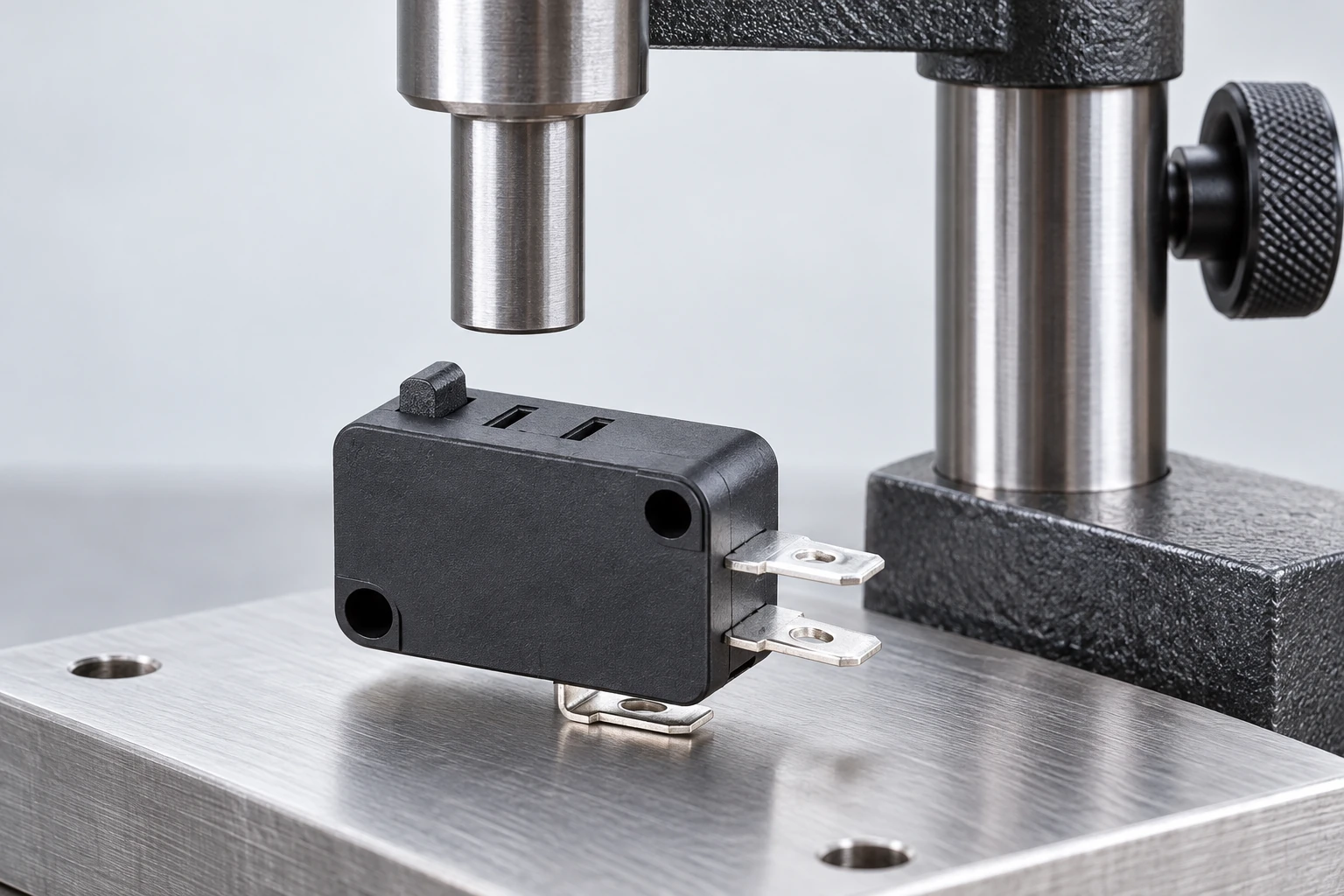
Define an operated position with margin
The nominal operating point is not automatically a suitable final resting position for the machine target. Account for the permitted working travel, the component tolerances and the movement that remains available after the contact changes. The target must provide the intended operated condition without driving the switch beyond its allowed travel.
The margin also has to survive the assembly. Bracket deflection, cam runout, thermal movement, fastener seating and wear can shift the relative positions. A test performed with a rigid laboratory finger may therefore miss a problem in a flexible production mechanism. Document the actual mounting and target geometry instead of treating a catalogue operating position as the finished equipment setting.
Do not invent a universal extra distance. The correct clearance and working travel depend on the switch variant and machine drawing. Where the documentation is incomplete, ask for the missing range rather than compensating with deeper actuation.
Investigate dwell near the threshold
A machine may intentionally stop close to the changeover region, or arrive there because of tolerance, slow motion or backlash. Record whether the target is actually stationary. Small reversals from a vibrating bracket, gear clearance or operator hand movement can repeatedly cross the operating and release regions.
Observe both approach directions. The switching point during approach and the release point during withdrawal need not coincide; that separation is part of the mechanism’s behavior. The application should not rely on an unverified assumption that a motionless-looking target always provides an unambiguous electrical state.
A useful review separates target motion from contact behavior. Secure and inspect the fixture, establish the intended positions, and then evaluate representative motion under the actual input conditions. Do not hold an energized contact at a deliberately marginal position as an improvised endurance test. A laboratory investigation needs an agreed procedure, appropriate instruments and acceptance criteria.
Keep the electrical input in the investigation
A closed contact and a recognized controller input are related but separate results. Input current, thresholds, wiring, filtering and sampling can influence what the controller sees. A high-current component rating does not by itself establish reliable low-level signal behavior. Check the input manufacturer’s documentation and the selected switch’s applicable minimum-load information.
An isolated continuity check is useful for identification and an initial static state check. It does not characterize every short transition, signal level or controller response. Select instruments whose resolution answers the actual question. If the equipment event is missed only during slow motion, compare the raw contact signal with the processed input state and the position record before adding software delay.
Build a representative slow-motion test sequence
Begin with identification and an unpowered mechanical review. Confirm the actuator, mounting, direction of approach and available release clearance. Inspect for side loading, binding and an external stop that incorrectly uses the switch as a structural limit. Correct obvious mechanical problems before collecting electrical traces.
Then follow a defined sequence covering the slowest intended approach, the normal dwell, the longest anticipated pause and the complete withdrawal. Include startup and reversal conditions when they occur in service. Repeat across representative samples and assembly extremes rather than proving only one carefully adjusted specimen.
Record the test configuration, instrument settings and pass criteria beside the observations. The Orientação da HSE para testes elétricos explains why testing arrangements need controlled access and safe procedures. This article supplies review questions, not permission to probe a live machine.
Compare observations before choosing a correction
| Observed behavior | Boundary to investigate | Useful next record |
|---|---|---|
| Repeated state changes during dwell | Target motion and threshold crossings | Position trace beside raw input state |
| No recognized command after contact operation | Input interface and event duration | Raw contact and controller-recognized state |
| Actuator remains operated after withdrawal | Mechanical return and clearance | Target and actuator positions during return |
| Only one adjusted specimen works | Assembly tolerance and support stiffness | Representative extremes and mounting condition |
| Stable static path but intermittent operation | Dynamic mechanism and input conditions | Controlled motion sequence with stated resolution |
Use these distinctions to locate the cause rather than automatically replacing the switch. A mechanical setting correction, a different actuator arrangement and an input-interface correction are different engineering changes. Each needs its own evidence and a repeat of the affected checks.
Treat filtering as a defined system decision
A filter may reject unwanted transitions, but it can also delay or remove a legitimate event. Establish the shortest valid event and the allowed response time before selecting a delay. A filter cannot create release clearance, eliminate side loading or approve operation outside the manufacturer’s stated conditions.
Where the machine requires a stable state over a long dwell, determine whether the mechanical target can occupy a position with documented margin. Where the application requires an edge, establish which edge is meaningful and how repeated threshold crossings should be handled. These requirements belong in the equipment specification, not in an undocumented service adjustment.
O operating-speed and frequency article addresses permissible movement and repetition. Keep those limits in the same review, while preserving the separate slow-threshold stability question discussed here.
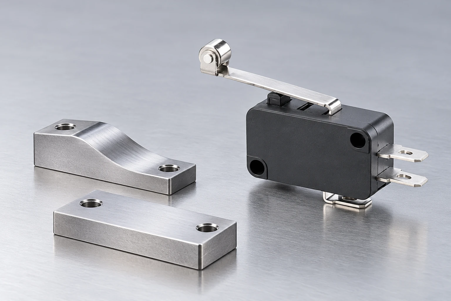
Ask for model-specific evidence without assuming a feature
Describe the actual slow-motion problem in an inquiry: complete order code, actuator variant, target sketch, direction, speed range, final positions, dwell time, load and input circuit. Include representative traces when available. Ask which operating conditions, motion limits and test methods the supplier confirms for that exact variant.
Words such as “snap action” or “precision” do not replace the evidence. Similarly, a competitor’s technical note can help explain terminology without proving that another manufacturer’s product has the same internal construction or performance. The IEC 61058-1 catalogue entry identifies the scope of general appliance-switch requirements; it does not provide a product-specific slow-actuation approval.
Keep a useful acceptance record
A complete record should identify the switch and assembly revisions, the tested samples, the position references, the electrical circuit, the measurement settings and the observed state sequence. State the slowest tested movement and the dwell conditions. Record whether those represent the full intended application or only an exploratory bench check.
If a different lever, spring, bracket or controller filter is proposed later, review whether it changes the validated margins. The objective is a reproducible assembly behavior that another engineer can inspect, rather than an informal statement that the switch “clicked correctly.” For product and sample discussion, send the mechanism record through the LEMA inquiry page.
Further learning: observing mechanical motion
nptelhrd: Module 14 – Lecture 1 – Vibration Measurement. This NPTEL lecture explains observation of mechanical motion. Use it as background for relating a motion record to an electrical event; it does not demonstrate a KW7 test or establish slow-actuation limits.
Watch Module 14 – Lecture 1 – Vibration Measurement.
Perguntas frequentes
Does snap action guarantee every slow approach will work?
No. Internal switching behavior does not approve an arbitrary target position, dwell, load or input circuit. Confirm the exact model conditions and validate the complete mechanism with sufficient operated and released margin.
Is repeated switching near the threshold always contact bounce?
No. A target that reverses or vibrates across the operating and release regions can cause repeated genuine operations. Compare position and electrical state before assigning the symptom to transient contact bounce.
Can I fix a marginal mechanism with a longer software delay?
Only an approved system decision can set filtering. A delay can suppress valid events and cannot supply missing travel, return clearance or an acceptable actuator approach. Correct the physical boundary and verify the required response.
Does this article prove that KW7 is tease-proof?
No. The KW7 illustrations identify a real product family, not a tested internal performance claim. Request the exact variant specification and appropriate evidence for the proposed slow-motion application.