
Micro switch vibration and shock resistance must be evaluated as both mechanical survival and electrical behavior. A switch can remain physically intact yet produce an unwanted contact transition while the equipment vibrates. Conversely, a contact that appears stable during a short observation does not establish long-term structural durability. Compare the test waveform, frequency or pulse duration, severity, direction, mounting, actuator state and monitored contact behavior before selecting a part. A single acceleration number is not enough to approve a switch for an OEM mechanism.
O LEMA KW7 micro switch family page lists vibration resistance and separate shock-related entries for destruction and malfunction. Those distinctions are useful starting points for a technical inquiry. They do not establish that every variant or finished machine has passed your application’s test. Obtain current documentation for the full order code and confirm the conditions behind the rating.
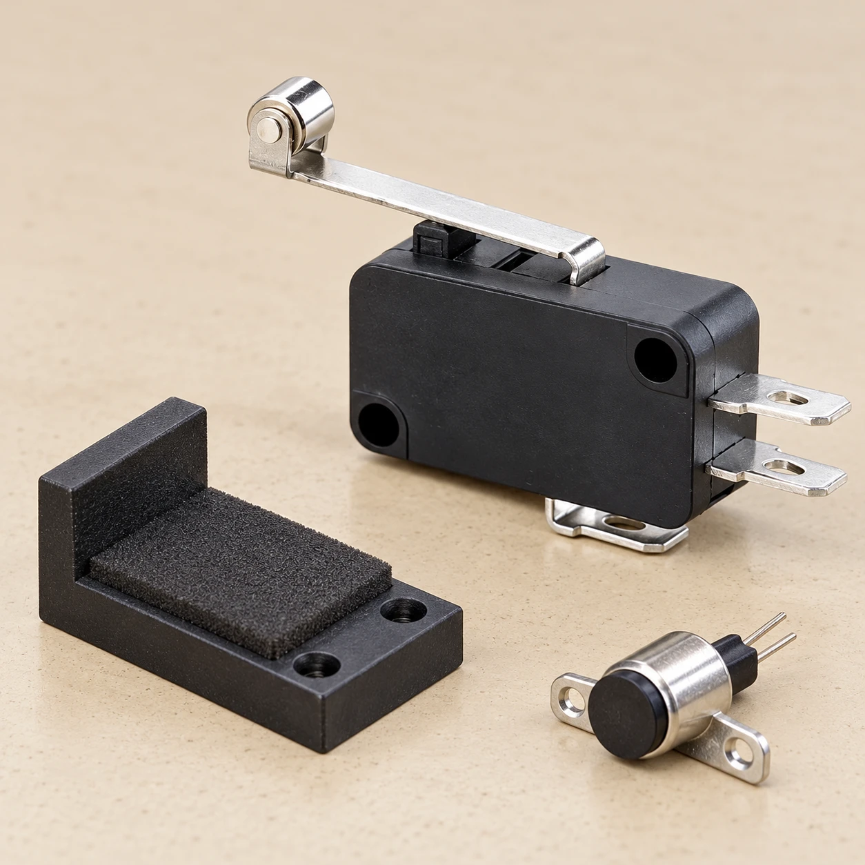
Separate a continuous vibration exposure from a shock pulse
Vibration describes oscillatory motion. A machine may expose a component to repeated excitation over a range of frequencies, and the supporting structure can affect the motion at the switch itself. Shock describes a transient event, such as a specified pulse associated with an impact. These exposures are not interchangeable, even if both are described using acceleration. Duration, repetition and the way the energy enters the assembly matter.
The IEC catalogue describes IEC 60068-2-6 as a sinusoidal vibration test method e IEC 60068-2-27 as a shock test method. The methods need a relevant specification to define the exposure and acceptance conditions. Citing either standard’s name without a test severity and result does not prove a component is suitable for a particular machine.
| Pergunta | Evidência a solicitar | Misleading shortcut to avoid |
|---|---|---|
| What vibration was applied? | Waveform, frequency range, displacement or acceleration definition, duration and axes | Comparing frequency alone |
| What shock was applied? | Pulse shape, peak acceleration, pulse duration, repetition and directions | Comparing peak acceleration alone |
| Did the housing survive? | Post-test inspection and specified functional checks | Assuming an intact housing proves stable contacts |
| Did the electrical state remain acceptable? | Contact state, monitoring circuit and permitted interruption or transition criterion | Using a visual indicator as a fast event detector |
| Does the result represent the machine? | Fixture, mounting hardware, actuator position and installed assembly comparison | Transferring a bare-component result directly to an unsupported bracket |
The table organizes a document review; it does not prescribe universal test severities. Use the applicable specification and laboratory procedure to set the actual conditions.
Understand destruction and malfunction as different acceptance questions
A destruction-related rating concerns resistance to a specified exposure without unacceptable physical damage or loss of required performance. A malfunction-related rating concerns unwanted behavior during the exposure under defined monitoring conditions. The exact definitions belong to the manufacturer’s test specification. Do not infer the permitted contact interruption time from the word malfunction alone.
A practical distinction is whether the switch still works after the shaker stops versus whether its contacts maintained the required state while the shaker was running. Both can matter. A position input may report an unwanted machine event during vibration and then return to normal, leaving no obvious visible damage. A damaged mounting ear may also allow a switch to pass one electrical observation yet fail to retain its position later.
The KW7 family page differentiates some shock values by operating-force category. This is a reason to ask for the exact variant’s data, rather than selecting the largest number on the page. A lever variant changes the external actuation arrangement, and the complete order code should accompany the report. Do not assume that a stronger operating force, a shorter lever or a heavier housing automatically guarantees better system behavior.
Translate the real machine exposure into a test request
Start with where the component is mounted and what the equipment does. Record whether the exposure arises during normal running, a specific machine cycle, transportation, handling or a fault. An operational test with the switch actuated answers a different question from a packaged transport test. Keep the product’s shipping protection separate from the fixture and support used in service.
Where measurements are available, identify the sensor location and direction, the machine state and the recording conditions. A value measured on a motor casing is not necessarily the motion at a remote switch bracket. Ask an appropriately equipped laboratory or vibration specialist to translate field observations into a justified test profile. Avoid inventing a laboratory severity from a subjective description such as moderate vibration.
For an initial inquiry, photographs and a mounting sketch are useful alongside the expected environment. Show the bracket, fasteners, actuator target and cable support. State which contact transition would be unacceptable and how the controller responds. This lets the supplier identify whether an existing component report addresses the question or whether assembly-level evaluation is needed.
Control the mounting arrangement before comparing parts
The fixture is part of the test boundary. Identify the approved mounting surfaces, hole positions, hardware and tightening procedure. A flexible bracket can introduce a different response from a rigid laboratory plate, while a cable left unsupported can transmit forces to the terminals. A test report that omits the support arrangement is difficult to apply to a production assembly.
Do not clamp a micro switch through its cover, lever or terminal blades merely because that makes the fixture convenient. Use the mounting features and procedure approved for the exact component. Excessive clamping can distort a housing; insufficient retention can allow movement. The applicable torque should come from the controlled installation documentation, not from a generic fastener chart used without considering the molded component.
Record any change in the fixture or cable routing between samples. If a candidate switch requires a new adapter plate, compare the complete installed arrangement instead of attributing every difference to the switch mechanism. A successful result with one bracket is evidence for that configuration and test scope, rather than a blanket approval for other installations.
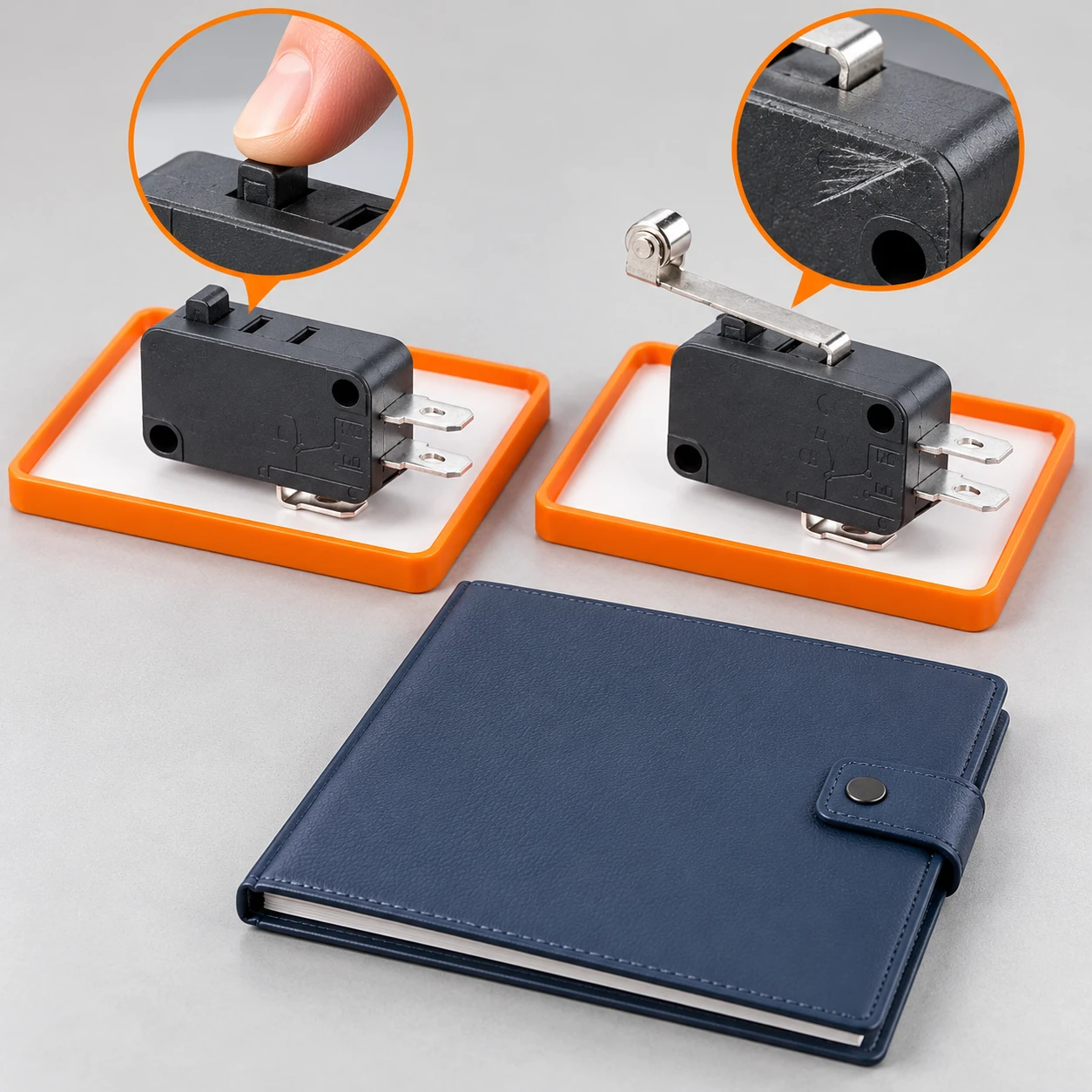
Define the actuator state and electrical monitoring
State whether the actuator is released, depressed to a defined working position, or moved during the exposure. Also identify the contact arrangement and the terminal pair being observed. A mechanism held close to its switching point can have a different margin from one placed correctly within its permitted working travel. Correct the mechanical operating window before interpreting vibration as a component defect.
Monitoring must be able to detect the event you care about. A panel lamp, a slowly sampled data logger and an oscilloscope do not necessarily observe the same transitions. Specify the relevant time resolution, input circuit and acceptance rule with the laboratory. Keep the raw contact behavior separate from filtering applied in the controller so that the test does not silently hide a problem.
Software debouncing may be part of the equipment’s normal design, but adding more filtering can delay recognition of a real position change. Evaluate that tradeoff at the machine level. For the separate subject of rapid transitions caused by contact mechanics, see micro switch contact bounce. A bounce investigation and an environmental vibration test should retain distinct exposure and acceptance records.
Inspect after exposure and preserve the evidence
Before testing, document the sample condition and the required baseline checks. After exposure, repeat the checks specified by the test plan and inspect the housing, mounting features, actuator and terminations. Record whether a change is cosmetic, dimensional, mechanical or electrical. A photograph by itself cannot establish the cause of a crack or prove that a contact event occurred at the same time.
When the result is unacceptable, retain the sample and fixture records. Compare failure timing with machine motion, monitored contact state and any observed mounting movement. Do not disassemble or clean a sample before deciding what evidence needs to be preserved. A structured investigation can distinguish a loose terminal connection, an actuator hovering near transition, a fixture issue and internal switch behavior.
For a broader fault investigation, the micro switch failure modes guide covers evidence collection across different symptoms. Use the guia de seleção de micro-interruptores industriais to place environmental requirements alongside load, travel, mounting and product documentation. Neither replaces a specified vibration or shock qualification.
Approve the configuration and manage later changes
An approval record should identify the switch order code, drawing revision, sample lot, mounting configuration, actuator arrangement and test report. Include the exposure, the monitoring criterion, deviations and the engineering disposition. Separate a supplier statement from a measured result and from the customer’s final equipment acceptance. These are connected pieces of evidence, but they are not interchangeable.
Review changes that could affect the result, including a different lever, bracket, fastener, cable assembly or controller filter. The appropriate response may be a document review, a limited comparison test or a new qualification, depending on the change and applicable requirements. A purchasing substitution based only on matching external size can miss the features that established the original acceptance.
Send LEMA the complete application and evidence request before freezing the component selection. Ask which existing report covers the proposed variant and installation conditions, and identify any remaining equipment-level work. This produces a more useful answer than asking whether a whole product family is vibration proof without defining the environment or permitted contact behavior.
Further learning: vibration measurement
NPTEL’s university lecture Module 14 – Lecture 1 – Vibration Measurement, from the Dynamics of Machines series, explains the measurement background needed to discuss motion and vibration. It is independent educational material, not a demonstration that the illustrated LEMA switches have passed a specific test.
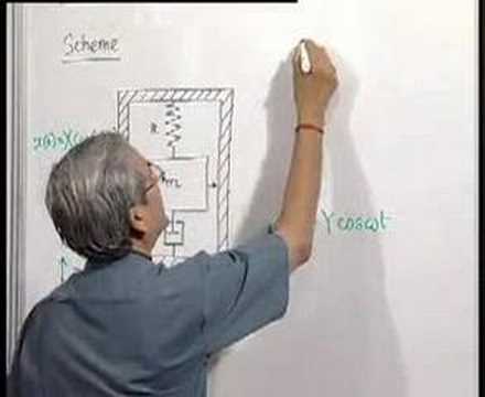
Watch the NPTEL vibration measurement lecture.
Perguntas frequentes
Does an intact housing mean the switch passed a vibration test?
No. Acceptance can also require specified electrical behavior during exposure and functional checks afterward. The test plan must define both physical and performance criteria.
Can I compare two shock ratings using acceleration alone?
No. Compare pulse shape, duration, repetition, direction, mounting, sample state and acceptance conditions as well as peak acceleration.
Can controller debouncing replace environmental qualification?
No. Filtering can change what the controller observes, but it does not establish structural durability or correct mechanical installation and may delay recognition of a real event.
Does a bare-switch report approve my complete machine?
No. Confirm how the tested configuration relates to the installed bracket, actuator, cable support and electrical interface, then complete the required equipment assessment.