
A 24V push button switch becomes a PLC digital input when its dry contact closes a low-current 24V DC loop that matches the input module’s sinking or sourcing common. This article walks through that interface logic, the difference between passive buttons and PNP/NPN sensors, how illuminated operators split contact and lamp paths, and the commissioning checks OEM panels need before ladder logic is trusted.
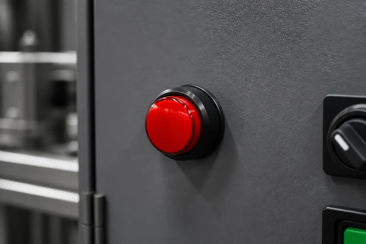
The panel scene below mirrors the operator-to-input topic of this guide.
Use this list to jump through the interface notes.
- What a PLC Push-Button Interface Actually Does
- Sinking vs Sourcing Wiring for Dry-Contact Buttons
- Why Push Buttons Are Not Wired Like PNP/NPN Sensors
- Illuminated Operators: Contact Path vs Lamp Path
- Commissioning Checks Before You Trust the Ladder
- OEM Notes When Specifying a Panel Push Button
- Choose PBS Series Push Button Switch for Panel Interfaces
- FAQ
- References
What a PLC Push-Button Interface Actually Does
It closes a low-current 24V DC sensing loop into a discrete PLC input—nothing more exotic than that.
A digital input module detects whether a field device is open or closed by watching voltage or current at the terminal. In a typical 24V control circuit, the push button, the input point, and the power supply form one continuous loop. When the operator presses the button, the contact finishes that loop and the module reports an ON state to the CPU.
That current is small. Educational PLC material commonly describes digital input current as usually under 10 mA, but the exact ON/OFF thresholds still come from the module datasheet for your rack. Treat the button as a signal device for the PLC, not as a substitute for a power contactor.
Many modules use an opto-isolated input front end, so the field wiring stays galvanically separated from the logic side. The practical takeaway for panel designers is simple: land the contact so the sensing LED inside the module can light when the operator presses the button, then confirm the same transition in the programming software.
Sinking vs Sourcing Wiring for Dry-Contact Buttons
Match the button polarity to the module common, then keep every point on that common bank consistent.
Sinking and sourcing describe the direction of conventional current between the field device and the PLC input. The terms apply to DC circuits. They do not describe AC input modules the same way.
| Module mode | Typical COM connection | Dry-contact push button wiring | What “ON” usually means at the terminal |
|---|---|---|---|
| Sinking input | COM to 0 V (DC−) | Feed +24 V through the NO contact into the input point | Input sees a positive voltage when pressed |
| Sourcing input | COM to +24 V (DC+) | Feed 0 V through the NO contact into the input point | Input is pulled toward 0 V when pressed |
Shared commons matter. If eight inputs share one Common terminal (COM), wire the whole bank the same way.
Mixed polarities on one common create a frequent commissioning trap. Those banks then produce inputs that never turn on, or that look permanently true.
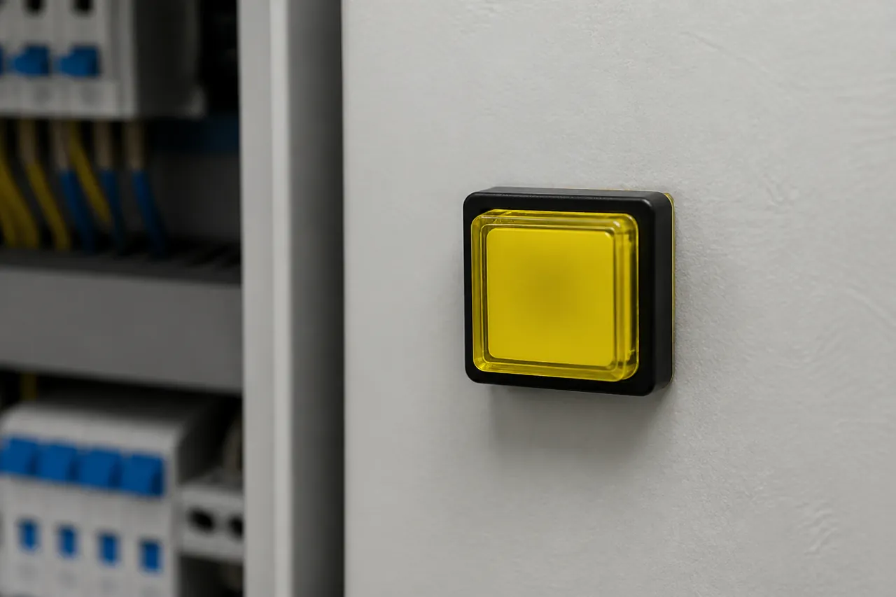
The contact block under the operator is what lands on the digital input terminal strip.
Important: Match the push-button circuit voltage to the digital input rating — source: AutomationDirect sinking and sourcing concepts. Applying a higher voltage class than the module allows can destroy the input front end.
Keep AC supplies off DC sink/source input points.
Why Push Buttons Are Not Wired Like PNP/NPN Sensors
Buttons are passive dry contacts; three-wire sensors are polarity-fixed devices.
A mechanical push button does not contain a PNP or NPN output transistor. Current can pass either way through the contact, so the same operator can support a sinking or a sourcing input bank once you choose which side of the supply the contact switches.
Active sensors are different. A PNP / NPN sensor output is polarity-fixed, unlike a dry-contact button.
A PNP (sourcing) sensor must pair with a sinking input. An NPN (sinking) sensor must pair with a sourcing input.
Installers who force push buttons to “follow the NPN sensor group” create unnecessary RFQ confusion. Community technicians often ask whether a controller “needs PNP or NPN,” and for sensors the useful answer is pairing.
On a mixed panel, keep sensor polarity rules for the sensor terminals, and treat start/stop operators as unbiased switches that simply complete the bank’s chosen polarity.
From the field: Forum installers often ask whether push buttons must be wired like NPN sensors on the same PLC — source: community wiring threads summarized via Arduino Forum PNP/NPN discussion. Experienced replies emphasize that a regular contact switch can sit on either the sinking or sourcing side, while solid-state sensors cannot.
Illuminated Operators: Contact Path vs Lamp Path
Use the contact for the digital input; power the LED on its own circuit.
An illuminated / LED push button adds a lamp path beside the switching contact.
In a documented Click PLUS lab build, the normally open contact feeds the PLC input while the lamp is driven from a PLC output return path. That separation keeps sensing current independent from lamp current.
When you specify an illuminated push button for 24V OEM work, document two circuits on the schematic: the dry-contact DI path and the lamp supply/return path. Do not assume one pair of terminals does both jobs.

Keep the lamp circuit notes next to the contact circuit on the drawing.
On the LEMA PBS Series Push Button Switch page, LED light is an ordering option (L: With LED or without LED). That option matters for panel graphics and night visibility, but it does not replace the sink/source decision for the contact that lands on the PLC input.
Commissioning Checks Before You Trust the Ladder
Prove voltage, COM mode, and software status before blaming logic.
- Read the input module label for voltage class and sink/source (or configurable) mode.
- Trace the COM terminal to +24 V or 0 V and write that mode on the terminal strip.
- Land one side of the NO contact to the supply pole required by that mode; land the other side to the assigned input.
- Use ferrules on stranded control wire at screw terminals when the hardware allows—stranded whiskers are a frequent short risk on dense PLC rows.
- Press the button and confirm both the module status indicator and the online input bit.
- Measure voltage at the terminal if the LED and the software disagree. LED alone can mislead when leakage or floating inputs are present.
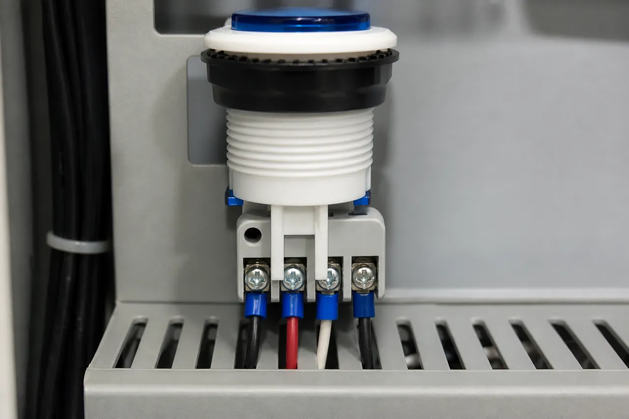
Terminal access is where ferrules and polarity checks pay off during commissioning.
If the input stays ON regardless of the button, re-check COM polarity and look for a welded or mis-landed contact that permanently completes the loop. If the input never turns ON, confirm the bank mode, the supply polarity through the contact, and that you did not place an AC circuit on a DC-only input point.
OEM Notes When Specifying a Panel Push Button
Document voltage, module mode, contact form, LED need, and colour—without inventing unpublished ratings.
| Spec item | What to write on the OEM drawing / RFQ note |
|---|---|
| Control voltage | 24V DC digital input circuit (match module rating) |
| Input mode | Sinking or sourcing; COM polarity for the bank |
| Contact role | Dry-contact NO (and NC if used) as PLC DI, not motor load switching |
| Illumination | LED required or not; separate lamp circuit noted |
| Operator colour | Colour code for the panel legend |
| Evidence boundary | Request datasheet values for ratings, IP, or cutout before claiming them |
Buyers sometimes ask for “PLC-compatible push buttons” as if compatibility were a single SKU flag. Compatibility is a wiring and rating match: the contact must handle the module’s sensing circuit, and the mechanical operator must fit the panel design. If a datasheet value is missing from the public product page, leave it blank on the claim list and ask for the drawing package instead of guessing.
Colour coding still helps operators. The PBS ordering table lists R, Y, B, G, P, and W. Use those codes to keep start, stop, and mode buttons visually consistent across machines built for global customers.
Choose PBS Series Push Button Switch for Panel Interfaces
Consider PBS when you need colour and optional LED operators for automation panels that feed 24V PLC inputs.
After the interface rules above are set, the remaining product decision is which operator family covers the panel’s colours and illumination needs. The PBS Series Push Button Switch is a snap-action push button series aimed at industrial and commercial equipment, including automation panels. The public page documents LED ordering, the six colour codes, and notes that some models can be equipped with KW7 series micro switches.
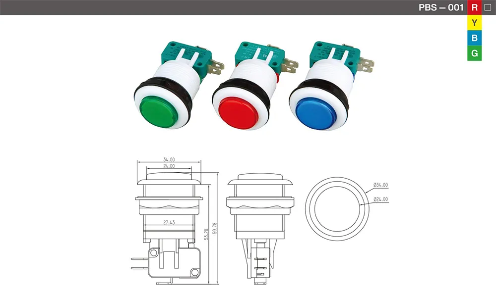
Review the colour and LED ordering fields before freezing the panel legend.
Choose another path when the project requires verified IP performance, a certified emergency-stop function, or published electrical ratings that are not shown on the current product page. In those cases, keep the interface notes from this article and request model-level evidence before freezing the BOM.
FAQ
How do you wire a push button to a PLC input?
Complete a DC loop through the button contact and the input point.
For a sinking bank with COM at 0 V, feed +24 V through the NO contact into the input. For a sourcing bank with COM at +24 V, feed 0 V through the contact into the input. Then prove the bit in software.
What is the difference between sinking and sourcing PLC inputs?
Sinking inputs accept current into the module toward the common return. Sourcing inputs supply current out of the module toward the field device. The push button only has to switch the correct supply pole for the mode you chose.
Are push buttons PNP or NPN devices?
No. Mechanical push buttons are dry contacts without a fixed transistor output type.
PNP and NPN labels belong to active sensors. Wire the button to match the PLC input mode instead of forcing a sensor label onto it.
Why does a PLC input stay ON after I wire the push button?
Common causes include reversed sink/source assumptions on the COM terminal, a contact landed so the loop is always complete, or a module bank sharing a common that was polarized for a different field device style. Re-trace COM, measure the terminal, and compare the online bit.
Does an illuminated push button need a separate path for the LED?
Usually yes. Keep the dry contact on the digital input circuit and power the lamp or LED on its own supply/return—often from a PLC output in lab examples. On PBS, LED is an ordering option and should be treated as a separate functional choice from the contact wiring.
Can I mix proximity sensors and push buttons on one input bank?
Yes, if every device on that shared common is wired for the same sink or source mode. Sensors must match the module type; push buttons can be polarized to follow the bank. Do not mix opposite polarities on one COM.
What should OEM buyers confirm before ordering a panel push button for PLC use?
Confirm 24V DC input rating match, sink/source mode, NO/NC contact needs, whether LED illumination is required, colour codes for the legend, and any datasheet items not published on the marketing page. Then select a family such as PBS only after those notes are written.