
ultra miniature micro switch became a priority because Google Search Console already shows real impressions for this topic on LEMA. That signal indicates an existing audience, but the previous site coverage did not fully match the question. This guide turns the query into a practical selection, integration and purchasing workflow for equipment designers, panel builders, maintenance teams and industrial buyers.
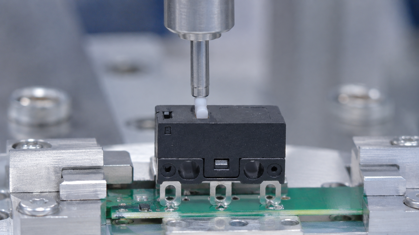
An ultra miniature micro switch saves volume only when its actuator, terminals and tolerance chain are designed together. Small housings usually leave less room for misalignment, soldering heat, board flex and excessive overtravel. Select the actuator by the motion presented by the product: a direct plunger suits controlled linear travel, while a lever can reduce operating force and absorb some approach variation. PCB models require special attention to hole pattern, seating, solder profile, cleaning process and mechanical support. The PCB should not become the stop that absorbs external impact.
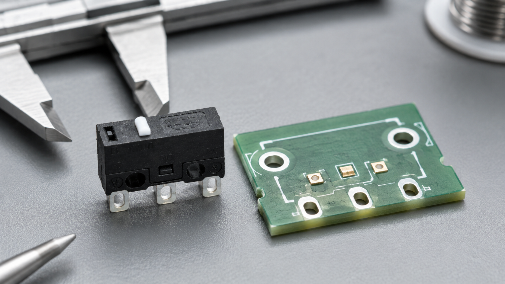
What ultra miniature micro switch means in a real design
A useful specification begins with behavior, not a catalogue photo. Write down what moves, what the operator or machine is trying to achieve, when the electrical state must change, and what should happen if a conductor opens or the device fails to reset. Separate the field device from the controller logic: a switch reports or commands a state, while the relay, PLC or control circuit decides how the machine responds.
Similar product families often contain several contact arrangements, actuator styles, terminal forms and mounting versions. The family name helps discovery but does not define a production part. Use the complete model suffix, revision-controlled drawing and terminal diagram. If any selection field is unclear, ask the supplier to mark the proposed configuration rather than accepting a verbal equivalence.
Selection checklist
| Interface | Risk in a small package | Control |
|---|---|---|
| Actuator | Side load or excessive travel | Guide the moving target and provide a stop |
| PCB pins | Hole or footprint mismatch | Use the exact recommended layout |
| Soldering | Heat damage or body distortion | Validate profile and fixture support |
| Contact load | Signal contamination or overload | Match rating and load character |
| Assembly | Flux, debris or cleaning ingress | Qualify the complete process |
Use this table as an RFQ gate. Each answer should point to evidence: a drawing dimension, datasheet condition, sample measurement or agreed inspection method. Numerical ratings are meaningful only with their stated voltage, current, load type, duty and environmental limits. A headline value copied from another model is not evidence.
Electrical function and contact logic
Identify the circuit state with the device released and operated. For changeover contacts, verify which terminal is common and which path is closed in each state. For a controller input, decide whether normally open or normally closed logic gives the desired diagnostic behavior. An open wire, loose connector and operated switch can otherwise appear identical to software.
Voltage and current are only the beginning of load review. DC interruption, inductive coils, lamp inrush, motor loads and low-level electronic signals stress contacts differently. Use the exact rating conditions and coordinate suppression, fusing and isolation with the system designer. The NIST explanation of the SI unit of electric current is a useful measurement reference, but it does not replace product-specific ratings.
Mechanical mounting and tolerance chain
Create a tolerance chain from the moving target or operator interface through the switch body to the panel, bracket or PCB. Include hole locations, panel thickness, coating, actuator approach, permitted travel, hardware stack, rear clearance and cable bend radius. Evaluate the worst acceptable combination, not only the nominal CAD assembly.
A switch should not become an unintended hard stop. Provide separate mechanical stops where the moving system can exceed the permitted travel or impact energy. Avoid side loading on plungers and uneven loading on panel bushings. Confirm that production workers can orient, tighten, connect and inspect the component without damaging adjacent wiring.
Environment, enclosure and service life
Describe the actual exposure: indoor dust, metal chips, oil mist, water jets, condensation, cleaning chemicals, vibration, temperature cycling or outdoor ultraviolet light. A front-panel boot or gasket protects only one ingress path. Rear terminals, cable entries, enclosure seams and every other opening determine the performance of the complete assembly.
Service life depends on electrical and mechanical conditions together. Operating frequency, force, impact, load type, contamination and temperature can make a catalogue cycle figure unrepresentative. For important programs, agree on a representative endurance test and inspect contact behavior, operating point and physical damage at defined intervals.
Safe installation sequence
- Control hazardous energy. Follow the facility procedure, isolate all relevant energy sources and verify the safe state before work.
- Confirm identity. Match the exact model, drawing revision, action and terminals to the approved bill of materials.
- Inspect the interface. Check holes, panel thickness, bracket alignment, cleanliness, edges and available service space.
- Mount without distortion. Seat hardware evenly and use documented torque or retention instructions where supplied.
- Terminate and support wiring. Control strip length, crimp or solder quality, insulation clearance, strain relief and bend radius.
- Test without power. Verify continuity and state transitions through the full mechanical range.
- Commission carefully. Check the controller input first, then machine response at reduced risk before normal operation.
The OSHA hazardous-energy guidance explains why isolation must be an established program rather than an improvised switch-off. The OSHA electrical-safety resources provide additional context for qualified work. Local laws, machine documentation and the site’s own procedures remain controlling.
Commissioning tests that reveal hidden errors
Test the physical device, controller input and final machine response as separate checkpoints. This makes it easier to distinguish mechanical misalignment from a wiring problem or inverted program logic. Repeat slow approach, normal approach, release, cable movement and the least favorable allowed alignment. Watch for chatter, delayed reset, abnormal sound, housing movement and inconsistent controller indication.
Where a command can expose a person to moving machinery, the risk assessment determines the required safeguards and safety architecture. A general-purpose control component should not be described as a safety-rated protective function without the required certification and system evidence. The OSHA machine-guarding introduction is a useful starting point for identifying hazards around moving equipment.
Common mistakes and corrective actions
- Selecting from appearance while ignoring the exact suffix and contact diagram.
- Treating a nominal rating as valid for every voltage, load and duty cycle.
- Ignoring tolerance, overtravel, side load, panel thickness or rear clearance.
- Assuming a sealed component makes the entire enclosure sealed.
- Using colour, position or a single label as the only operator cue.
- Testing one successful actuation instead of the full permitted range.
- Approving a sample without defining production inspection and change notification.
Most of these failures are inexpensive to prevent during drawing review. Bring mechanical, electrical, production and quality personnel into the sample review, and document every assumption that affects fit, function or safety. A short approved checklist is more valuable than a long email chain that never becomes a controlled requirement.
OEM RFQ checklist
Send the supplier the application and interface, not only the search phrase. State the function, normal and operated states, circuit voltage and load type, expected cycles, mounting drawing, actuator or operator interface, terminal and cable preferences, environmental exposure, annual quantity, packaging, target market and validation plan. Ask for the complete proposed part number, controlled drawing, material declarations where needed, lead time, sample availability and change-notification process.
For production acceptance, identify critical dimensions and functional tests. These may include contact state, operating point, terminal retention, visual defects, wire labels or lamp behavior. Use sampling and test limits appropriate to the consequence of failure. Preserve the approved sample and drawing revision so future lots can be compared against the same baseline.
LEMA product and related guides
Review the Micro Switch product range and the relevant LEMA product example. For adjacent questions, see this related selection guide and this installation or OEM guide. Final dimensions, terminals and ratings must be confirmed for the selected model.
Video explanation
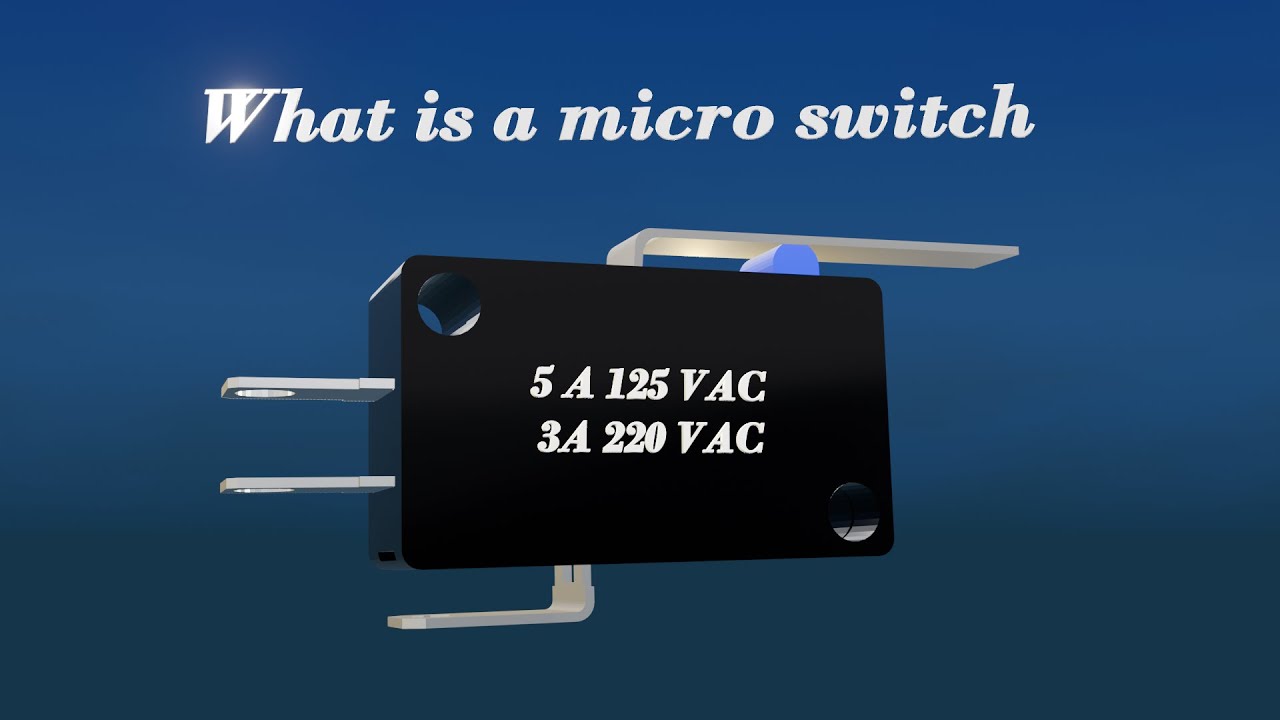
What is a micro switch | micro switch working | Understanding a Microswitch by FOCUS(I&C) gives a visual introduction to the relevant mechanism or installation concept. Use it as general education, then follow the drawing and instructions for the exact product.
Frequently asked questions
What should be checked first when selecting ultra miniature micro switch?
Define the required equipment function, normal and actuated states, load, mounting interface and environment. Then compare those requirements with the controlled drawing for one exact model.
Can two similar-looking switches be interchangeable?
Not safely by appearance alone. Terminal logic, dimensions, force, travel, ratings, sealing and production tolerances can differ even when housings look similar.
How should a sample be validated?
Inspect identity and dimensions, test every contact state without power, install it in the real interface, commission under controlled conditions, and repeat the most demanding permitted operating cases.
What belongs in an OEM quotation request?
Include the application, circuit and load, action, mounting drawing, environment, cable or terminal details, quantity, compliance market, packaging, traceability and acceptance tests.
Does this article replace the product datasheet?
No. It is an engineering selection framework. The exact model drawing, equipment documentation, risk assessment and applicable standards govern the final design.
Conclusion
A dependable ultra miniature micro switch decision connects function, contact logic, load, mechanics, environment, assembly and validation. Begin with the real equipment requirement, choose one documented model, test it in the full assembly and preserve the evidence used for approval. That process reduces redesign, avoids ambiguous substitutions and gives purchasing teams a much clearer basis for supplier comparison.