
Micro switch electrical life vs mechanical life compares two different endurance tests. Mechanical life counts operations at a stated speed and travel without an energized contact load. Electrical life counts operations while the contacts switch a specified voltage, current, and load type. The figures are not interchangeable, and neither is a calendar-life promise for a finished machine. A buyer should ask for the exact model’s test conditions, then compare them with the machine’s real actuation rate, overtravel, inrush, duty cycle, environment, and acceptable failure risk. This guide explains how to read those figures without inventing a life rating for a LEMA part that has not been tested in your assembly.
What is mechanical life?
Mechanical life, also called mechanical durability, describes the number of full switch operations achieved under a stated mechanical test, normally with the contact circuit not energized. An operation means the actuator is moved through its specified operating and release sequence, not merely touched. The test must define operation frequency, stroke or overtravel, operating speed, mounting, and the criterion used to call the switch failed. A mechanism can lose its snap action, spring force, return behavior, or dimensional stability even if no electrical load is switched.
The IEC 61020-1 publication description identifies electromechanical switches as devices that change an electrical connection through mechanical contact motion and says the generic specification addresses terminology and test methods. That is a useful framework, not evidence that any particular KW12 model meets a specific endurance value. For the mechanical side of a purchased model, request the manufacturer’s test report or datasheet and read its definition of a complete cycle and end-of-life failure.
In a machine, a lever that is struck hard by a cam, a plunger driven beyond its allowed travel, or a switch mounted on a vibrating bracket may see very different stress from a laboratory test. Likewise, a well-aligned actuator used at a controlled speed can behave differently from one experiencing side load. The number of cycles on a catalog page is therefore a comparison under stated conditions, not a permission to ignore the mounting design.
What is electrical life?
Electrical life, or electrical durability, is the number of operations achieved while contacts make and break an identified electrical load. A useful rating must identify at least voltage, current, AC or DC, load nature, operation rate, and failure criteria. The same switch can behave differently at a PLC input and at an inductive relay coil or motor circuit. A general current number alone is not enough to predict durability, because the stress at opening and closing depends on the complete circuit.
Under load, contact surfaces can experience arcing, heating, material transfer, pitting, welding, and changes in contact resistance. The severity depends on voltage, current waveform, inrush, inductance, contact material, opening behavior, and suppression. Research on electromechanical contact behavior from Marquette University’s electrical engineering publications illustrates why monitoring both contact resistance and contact force matters in switch reliability testing. That research concerns microfabricated contacts rather than a LEMA production switch, so it informs the physics only; it supplies no LEMA service-life figure.
Electrical life is commonly lower than mechanical life when a demanding rated load is switched, but the difference is model- and test-dependent. Do not assume a fixed ratio or convert one figure to the other. A switch that only signals a high-impedance controller input may face less switching energy than one directly interrupting a coil, yet low-level circuits have their own contact-material and signal-integrity requirements. Evaluate the actual circuit, not a generic “light load” label.
Mechanical life vs electrical life: what to compare
| Question | Mechanical-life evidence | Electrical-life evidence | Buyer action |
|---|---|---|---|
| Is the contact loaded during the test? | Normally unenergized. | Specified voltage, current, and load switched. | Confirm the exact test circuit and load category. |
| What counts as one operation? | Specified movement through actuation and return. | Specified movement plus make and break of the test load. | Compare the same cycle definition with the machine sequence. |
| What can limit the result? | Actuator, spring, housing, travel, return, or force drift. | Contact wear or welding, contact-resistance drift, plus mechanical limits. | Ask which failure criteria the test used. |
| What does the value predict? | Endurance in the stated unloaded test. | Endurance at the stated switched load. | Do not equate either to guaranteed calendar service life. |
| What must match the application? | Stroke, speed, actuation rate, alignment, environment. | All mechanical conditions plus voltage, inrush, AC/DC, load type, suppression. | Test production-intent samples in the real assembly. |
The table intentionally uses no universal cycle counts. A number without its test boundary is more likely to mislead than help. Request data for the exact part number and contact configuration. If a supplier offers an alternative actuator or terminal variant, confirm whether its durability evidence is valid for that variant rather than assuming one family-wide value.
Why the machine’s load changes the answer
A resistive test load is not a substitute for an inductive load review. An inductive circuit stores energy; opening the contacts can produce a voltage transient and arc unless the design controls it. A motor or lamp may create a high inrush at closing even when its running current appears modest. DC arcs can behave differently from AC arcs because the current does not naturally cross zero each half cycle. A protection device may reduce contact stress but can alter release time or introduce leakage, so it must be selected with the whole control circuit in mind.
A control input also needs evaluation. A PLC input may draw little current, but long cables, poor grounding, contamination, a mismatched contact material, or contact bounce can make a signal unreliable. For the specific relationship between contact resistance and function, see LEMA’s micro-switch contact resistance guide. It addresses measurement and symptoms, while this article addresses endurance definitions; the two topics should not be collapsed into one keyword target.
In a procurement specification, write the circuit terms explicitly: normal and maximum voltage, steady-state current, measured inrush, load type, switching frequency, contact arrangement, and any suppression network. If the switch controls a relay or contactor, record the coil’s actual characteristics and the protection circuit. A catalog electrical-life value can then be compared with a circuit that resembles its test conditions. Without that information, a predicted replacement interval is speculation.
Why actuator travel matters even for electrical life
The contacts cannot be evaluated independently of how the actuator is operated. Too little travel can cause marginal transfer or incomplete release. Too much travel or a hard mechanical strike can damage the case, lever, or internal mechanism. A very slow cam may change the force profile; a fast cam may increase impact. The selected lever changes the relationship between machine movement and internal switch travel. These variables can affect both the unloaded and loaded endurance of the assembly.
LEMA’s pretravel, overtravel and differential-travel guide explains the movement terms needed to interpret a switch drawing. The operating-force selection guide covers force and travel matching. For a real model, compare the operating and release positions, allowed overtravel, and permitted force with the cam geometry at both tolerance extremes. Do not use the micro switch as the machine’s end stop unless the equipment design explicitly validates that use.
How to turn cycles into an inspection plan without pretending to predict failure
A basic workload estimate helps size a test, but it does not transform a catalog rating into a warranty. Count actual actuation events in each operating mode. If a machine runs at different rates across shifts, calculate or log the expected cycles per day for each mode and combine them. Include startup, cleaning, homing, setup, and troubleshooting cycles where relevant. The resulting count indicates how quickly an endurance test might be approached; it does not guarantee when a failure will occur.
For example, if a switch operates twice per machine cycle, the daily switch count is twice the number of machine cycles, provided that the full actuation and release happen each time. If the machine occasionally jogs or rehomes, add those events rather than hiding them in an average. Then compare the application count with the exact-model electrical and mechanical test data and set inspection or replacement rules appropriate to the consequences of failure. This is a planning method, not a numeric recommendation for all factories.
Where a missed or stuck signal can damage equipment or injure people, a single switch’s published endurance is not a safety assessment. The machine needs a risk-based control design, appropriate fault detection, test intervals, and validation. Never describe a standard micro switch as a safety-rated interlock based solely on its cycle count or its contact arrangement.
What to request from a supplier before approving a switch
- Exact identity: model number, lever or plunger option, contact form, terminals, and drawing revision.
- Both endurance ratings: mechanical and electrical operation counts for that exact configuration, if available.
- Test conditions: voltage, current, AC/DC, resistive or inductive load, inrush, cycle frequency, actuation speed, stroke and overtravel, ambient conditions, and sample size.
- Failure criteria: allowable change in contact resistance, operating point, force, insulation, or inability to transfer and return.
- Application comparison: evidence that the intended load, mounting, and environment are within the stated ratings.
- Substitution control: a process to review any change in contact material, actuator, terminal form, or manufacturing revision.
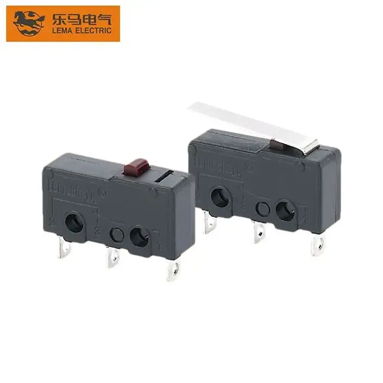
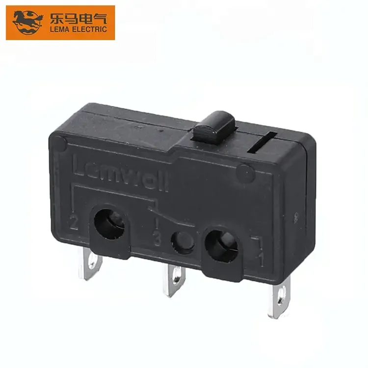
Review the LEMA KW12 micro-switch product family for its available construction and use its exact part drawing for the shortlist. The image and family description alone do not establish life under your load. The broader LEMA micro-switch range can help identify alternatives when force, envelope, or terminals differ. Ask for model-specific data before releasing production purchasing instructions.
Common mistakes when reading a life rating
One frequent error is quoting mechanical life to justify a loaded application. Another is reading a resistive electrical-life test as though it applies to an inductive coil or a motor. A third is assuming a higher cycle count means better reliability in every circuit. Small signal currents, contamination, contact material, and wiring can matter more than a headline cycle number. Finally, a different actuator option can alter mounting and travel conditions even when it uses a similar internal switch.
Qualification testing should use the actual bracket, cam, cable, controller input or load, and environmental exposure. Record the switch state at rest and at the machine’s worst-case positions. Observe any contact chatter or intermittent signal at operating speed. Periodically measure the relevant electrical and mechanical characteristics according to a defined method. This approach finds integration problems before a high-volume order, where a catalog-only comparison may miss them.
Video: seeing the mechanism that cycles
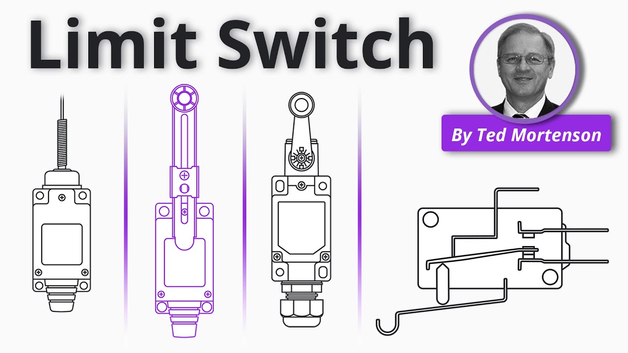
This RealPars explanation of mechanical limit-switch operation shows how actuator motion transfers a contact. A micro switch uses its own specified mechanism and dimensions, but the visual helps distinguish mechanical cycling from electrical loading. The video does not provide a KW12 endurance rating.
Frequently asked questions
Is electrical life always lower than mechanical life?
It often is under a substantial switched load, but there is no universal ratio. Compare the exact model’s stated ratings and test conditions. Do not calculate one from the other.
Does a PLC input mean electrical life no longer matters?
No. The energy may be lower than in a power circuit, but contact material, minimum load, wiring, contamination and signal quality still need review. Validate the input under real conditions.
Can I estimate years of service from a cycle rating?
You can estimate how many cycles your application accumulates, but a catalog test count is not a guaranteed failure date. Use application testing and consequence-based inspection planning.
Does a long lever increase the switch’s electrical life?
Not automatically. It changes the force and travel relationship. Electrical endurance still depends on the contact design, load and actual actuation conditions.
Conclusion
Mechanical life measures unloaded cycling under specified motion; electrical life measures cycling while a stated load is switched. For OEM selection, read both as bounded tests, document the real circuit and actuator motion, and qualify the exact switch in the finished assembly. The most useful supplier answer is not the biggest cycle number, but a traceable match between the test conditions and your machine.