
Power socket contact resistance adds electrical loss at the mating interface. Under a given current, a higher resistance produces more local power dissipation, but resistance alone does not predict the final temperature. The contact geometry, surrounding materials, ventilation and operating conditions also matter. For an equipment inlet, evaluate the complete mated connection and the actual application. Start with an isolated, repeatable resistance measurement and a qualified thermal validation plan. Do not use a continuity beep, a cool exterior surface or an unverified catalog number as proof that the connection is suitable.
This guide concerns panel-mounted equipment power sockets and inlets, rather than household wall receptacles or RV shore-power connectors. It focuses on how to interpret contact measurements and plan a heat-rise investigation. Work involving installed mains equipment requires qualified personnel, suitable test equipment and the equipment’s documented safety procedure.
Define the connection being measured
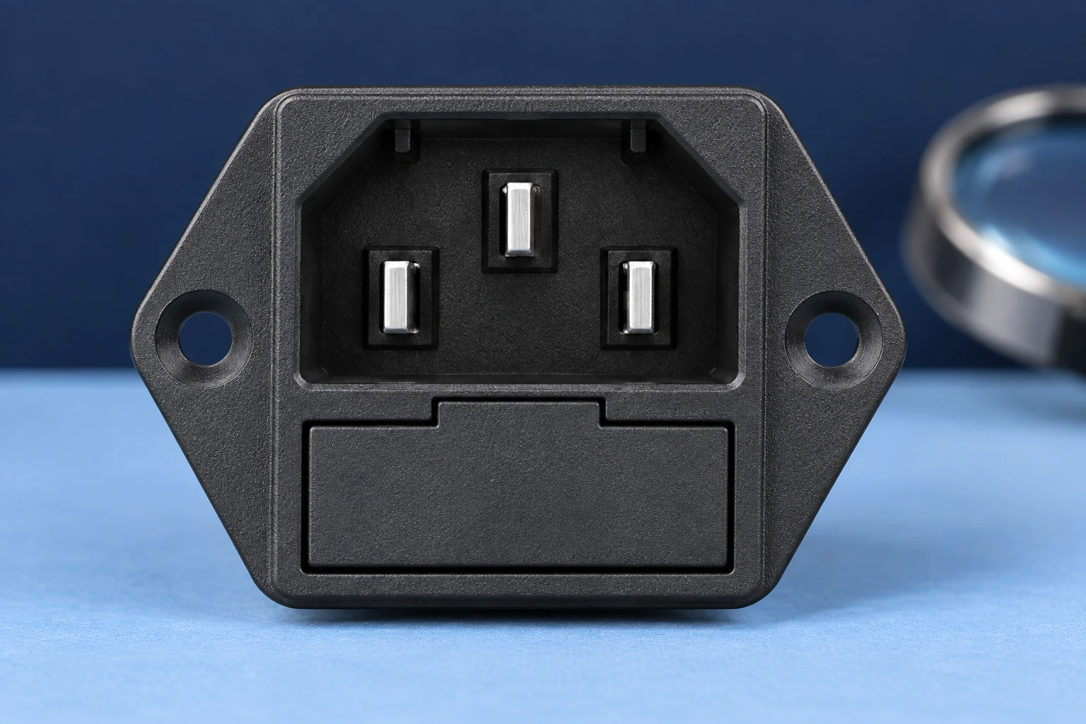
Identify the inlet, mating connector, terminals and measurement points. The resistance between two accessible points may include the mating interface, metal within the inlet, the cable termination and part of the cable. Without a clearly stated test boundary, two apparently different contact-resistance results may simply describe different paths.
Record the exact inlet and cord-set identities, their condition and whether they are fully mated. Preserve the mounting arrangement and cable support in the test record. A new loose sample on a bench is not necessarily representative of a connection installed in a warm enclosure. Conversely, a measurement including a long cable cannot be described as the inlet’s contact resistance alone.
The University of Maryland CALCE contact-resistance measurement overview describes evaluation using actual contact geometry and controlled environmental conditions. It supports a central practical distinction: measure the connection in a defined configuration, and retain the conditions needed to interpret or repeat the result.
Use electrical power to understand the heating mechanism
For a resistive section carrying current, the local power loss is P = I²R, where P is watts, I is amperes and R is ohms. The University of Colorado Boulder I²R heating demonstration illustrates the relationship between current, resistance and heat generation. For an AC calculation, use the appropriate RMS current and a resistance representative of the conditions being considered.
As an arithmetic example only, assume a measured resistive path of 0.010 ohm carries 5 amperes. The calculated loss is 5 × 5 × 0.010 = 0.25 watt. At 10 amperes with that same assumed resistance, the loss becomes 1 watt. These numbers describe a hypothetical path; they are not a LEMA specification, a permissible operating current or a verified thermal result.
Keep the units explicit. Convert milliohms to ohms before using the formula. A change in the written unit can change the calculated result dramatically. If a catalog unit is ambiguous, obtain written clarification rather than choosing the interpretation that seems plausible. Record the original document and the clarified measurement condition with the approval file.
For selecting between physical connection families, see the separate C14 equipment inlet selection guide. A connector designation and a headline rating do not replace evaluation of the real mated path.
Keep power loss separate from temperature rise
A calculated watt value is not a temperature in degrees. Temperature depends on how the generated heat moves through the contact, housing, termination, panel and surrounding air. Different installations can therefore reach different temperatures with the same measured electrical loss. Resistive heating is a reason to investigate; it is not a complete thermal model.
Define where temperature will be measured and which limit applies to that location. A contact interface, a terminal, a plastic surface and an accessible panel are different measurement points. Do not transfer an acceptance criterion from one point to another without the applicable product or equipment requirements. The hottest internal region may not be visible from an exterior thermal image.
Include ambient conditions, enclosure operation, load sequence and stabilization criteria in a qualified test plan. Keep the equipment in the arrangement used for approval, including adjacent heat sources and normal cooling. The plan should identify who is authorized to run the energized test and how the assembly will be made safe before any subsequent inspection.
| Question | Evidence required | What the evidence does not prove |
|---|---|---|
| Is the measured resistance repeatable? | Defined points, instrument method, mating state and repeated readings. | A repeatable number alone does not establish suitability under load. |
| How much resistive power is lost? | Current and resistance with compatible units and stated conditions. | Calculated watts do not directly establish temperature rise. |
| Where does the connection become warm? | Approved temperature measurements with locations and ambient conditions. | An exterior image does not necessarily show the hottest internal contact. |
| Did service change the connection? | Comparable baseline and later results, mating history and condition records. | A changed number does not identify the cause without investigation. |
| Does the assembly pass? | Applicable equipment and exact component criteria with a documented test. | A continuity beep or one successful power-up is not thermal acceptance. |
The table is a planning aid. It deliberately avoids a universal maximum resistance or temperature limit. The applicable criteria must come from the exact approved component, connection system and equipment requirements.
Choose a resistance method that matches the question
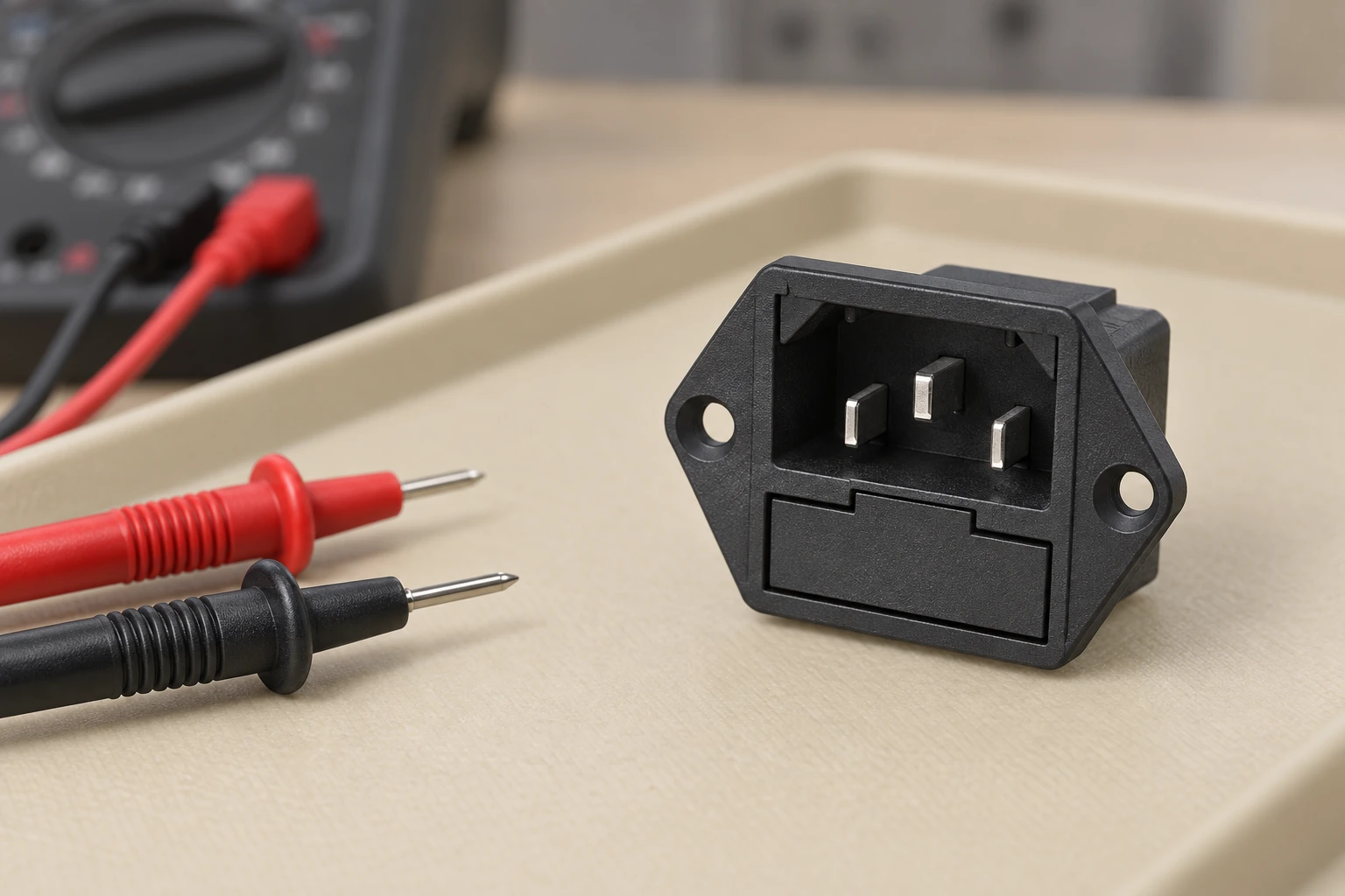
An ordinary two-wire reading includes effects from the test leads and their connections. For a very small resistance, those contributions can obscure the part of interest. A four-wire measurement separates the current path from the voltage-sensing path, allowing a more useful assessment when the instrument and fixture are suitable. It still requires defined contact points and a repeatable setup.
For the measurement principle, the University of Illinois explanation of four-probe measurement describes why an additional sensing arrangement can reduce unwanted contributions from contacts. Applying the principle to an equipment inlet requires an appropriate fixture; a general conductivity explanation is not an inlet test standard.
Document instrument identity, range, test-current conditions, sample temperature and the way each lead is attached. Do not change the contact pressure or mating condition simply to obtain a lower number. If the fixture itself changes the connection, the result may describe the fixture rather than normal use. Confirm that the proposed measurement does not unintentionally energize other equipment paths.
A continuity function can help identify an open circuit, but it usually answers a different question from a low-resistance evaluation. Use it as a screening observation. Do not turn an audible indication into an acceptance value unless the instrument method and the equipment requirement explicitly support that interpretation.
Investigate a changing value without guessing its cause
If readings change, first check whether the measurement setup changed. Review lead placement, fixture connection, instrument range and sample temperature. Then examine the defined mated connection and termination. Keep the original and repeated results rather than discarding an inconvenient value as an outlier without an explanation.
Record the mating history and any mechanical or environmental event associated with the change. An apparently similar replacement cord or connector may create a different interface. A connector that is not fully seated also changes the installation. Confirm compatibility from the approved documents instead of assuming that a part is acceptable because it can be pushed into place.
Do not bend contacts, apply improvised conductive material or force an unsuitable mating part to obtain a better reading. If damage, abnormal heating or instability is suspected, remove the equipment from service under its approved procedure and preserve the affected assembly for qualified investigation. The resistance result is evidence to interpret, not a reason to bypass an existing protective requirement.
Approve the assembly with a traceable baseline
Create an approval record linking the inlet, mating connector, termination and installed configuration. State the resistance method, thermal-test locations and acceptance criteria. Include the expected load and operating environment. This makes a later service investigation much more useful than a single unexplained number written on a sample bag.
Revisit the record when the cord set, terminal format, panel arrangement or operating load changes. Decide which checks must be repeated before release. A purchasing substitution that preserves the front dimensions can still require a new review of the complete connection. The panel-mounted power socket guide covers mounting considerations, while the C13 and C14 comparison explains the mating roles.
For a LEMA inquiry, provide the exact connection requirement, the mating part, the installed environment and the test criteria to be confirmed. The IPZ equipment power socket family supplies the real product reference used in these illustrations. Request a model-specific drawing and clarified units before using any resistance entry in an approval calculation. No catalog resistance value or certification is claimed as verified by this article.
Video: electrical power and resistive loss
Khan Academy explains electrical power in resistive circuits. The lesson helps interpret the I²R calculation used here. It does not demonstrate an inlet qualification test or provide a permissible contact temperature for a specific assembly.

Watch the Khan Academy electrical power lesson.
Frequently asked questions
Does a continuity beep prove that a power socket will stay cool?
No. It is a screening indication, not a resistance specification or thermal test. Evaluate the defined mated connection under the applicable equipment requirements.
Can I calculate contact temperature directly from I²R?
No. I²R gives resistive power loss in watts. Temperature also depends on the installation’s heat transfer and operating conditions.
Why use a four-wire measurement for low resistance?
Separating current and voltage-sensing paths can reduce unwanted lead and connection contributions. The fixture, measurement points and test conditions still need to be controlled.
Is there one contact-resistance limit for every equipment inlet?
No. Use the exact approved component and equipment criteria, with clear units and measurement conditions. Obtain clarification when a catalog entry is ambiguous.