
A foot switch cable should reach the intended operating position without pulling on the pedal, connector or internal terminals. Choose its length from the actual route, then verify conductor requirements, electrical interface, environmental exposure and strain relief. A longer cable is not automatically a better cable. Excess slack can create a trip or snag hazard, while a short lead can drag the pedal out of position. This guide covers industrial equipment command pedals, not amplifier accessories. The machine designer must approve the complete pedal, cable and control interface before operation; connector appearance alone cannot establish compatibility.
Start with the command circuit, not the cable length
Identify what the pedal actually controls. It may close a contact into a low-voltage controller, switch a relay circuit or form part of a manufacturer-defined interface. Those arrangements have different conductor, insulation and protection requirements. Do not assume that a familiar plug carries only a harmless signal. Read the equipment drawing, record the original pedal order code and confirm the supply and receiving input specifications before choosing a cable assembly.
A guitar footswitch cable may use a connector that looks similar to an industrial command lead. That resemblance does not prove matching pin assignments, contact action, protective-earth requirements or input behavior. Likewise, an audio shield does not automatically serve as a protective conductor. If the machine documentation is unavailable, keep the equipment out of service until its electrical interface can be established by a qualified person.
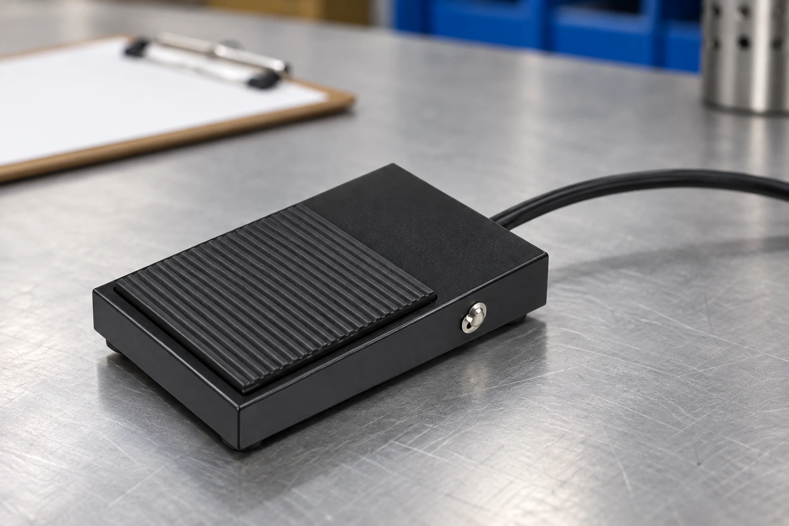
Use the LEMA LF foot switch product family as a starting point for a model enquiry. The reference photograph confirms an external pedal and attached lead; it does not establish the lead’s exact length, conductor size, pinout or suitability for a particular machine. Request those details for the selected order code rather than assigning them from a photograph.
Measure the route through every permitted pedal position
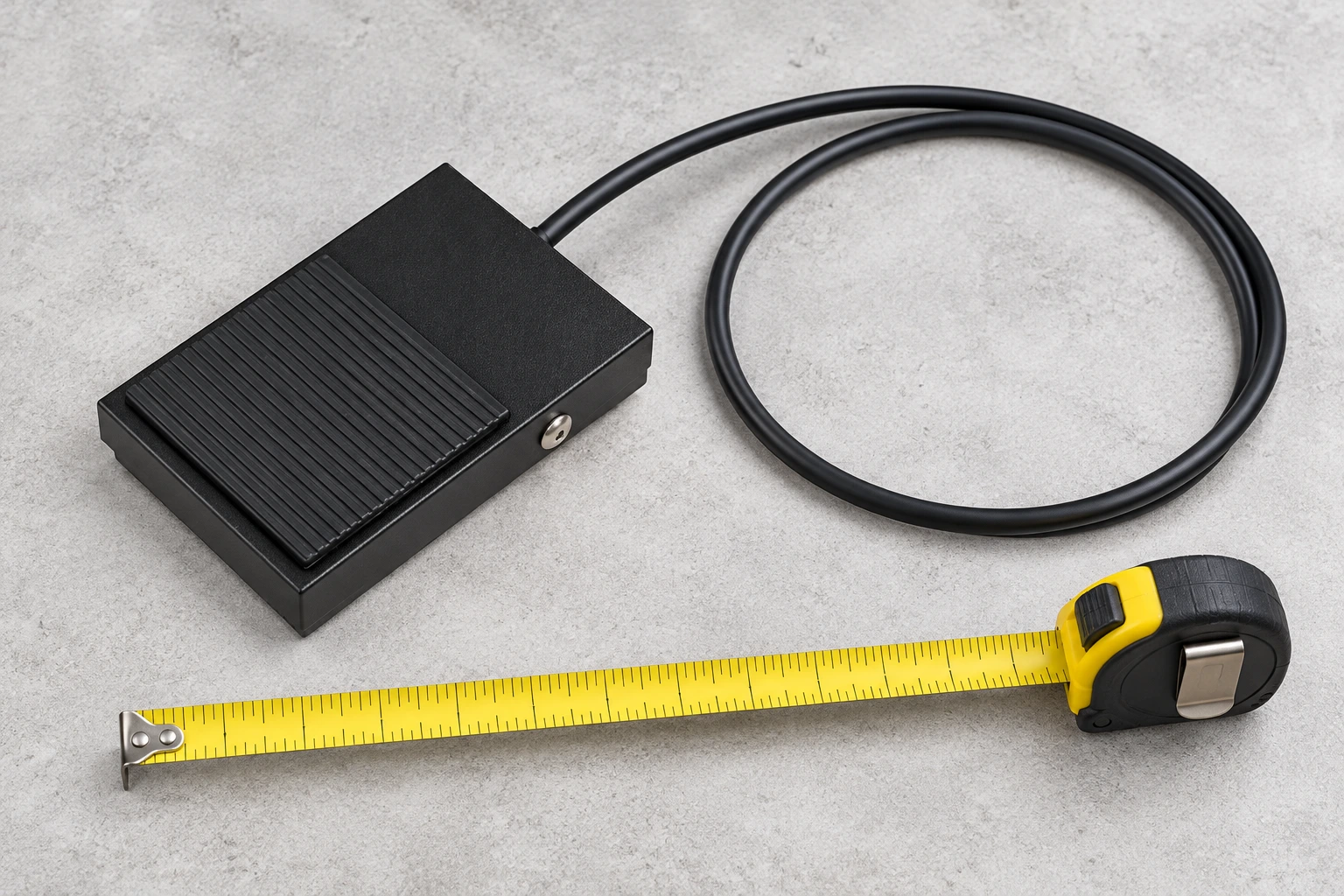
Measure along the proposed cable path from the pedal entry to the connection point. Include the route around the machine base, any protective channel and the movement needed to reposition the pedal within its intended operator zone. Straight-line distance between the two endpoints usually understates the installed requirement. Check the route with the machine and workstation in their permitted operating configurations, including a seated or standing operator where both are allowed.
Allocate service slack deliberately. The aim is to allow ordinary positioning and connection without tension, while keeping loops away from walkways, moving parts and material handling paths. A loose coil on the floor can catch a shoe, trolley wheel or workpiece. Fastening all slack tightly to the pedal can instead concentrate bending at the entry. Provide a documented storage or support location that can be inspected after cleaning and workstation changes.
No universal extra-length allowance or bend radius is appropriate for every assembly. Obtain the cable manufacturer’s installation and flexing limits, then check them against the selected routing hardware. Minimum bend radius for a static installation may differ from the requirement for repeated movement. If the pedal is routinely moved between stations, a cable designed only for occasional installation bends may be unsuitable even if it reaches both locations.
Give strain relief a separate acceptance check
Strain relief should stop an external pull from being carried directly by the electrical termination. The load should be retained by a suitable assembly feature, not by a solder joint, terminal screw or individual conductor. The presence of a black sleeve near the pedal is not proof that it provides the required retention. Inspect the assembly drawing and the approved test method for the exact cable and entry arrangement.
As a United States workplace reference, OSHA 1910.305 addresses flexible-cord suitability, strain relief and protection at openings. Its applicable requirements must be evaluated in the actual installation; this article does not certify an OEM assembly. An entry fitting should also protect the jacket from an enclosure edge. A clamp that holds the cable but cuts into its insulation solves one problem by creating another.
Check retention at both ends. An adequately supported pedal entry can still fail if the machine-side connector is unsupported and receives every pull. Verify that the plug body, cable grip, locking arrangement and mating receptacle work together. Do not pull the lead to disconnect the plug. For a factory-sealed pedal, request the supplier’s assembly and verification information rather than opening it and modifying the termination without an approved repair procedure.
Cable design review before purchase
Use a written comparison rather than a simple request for a longer lead. The qualitative checklist below separates interface, route and assembly issues so that a cable change cannot hide an incompatible electrical function. An unknown item is a request for evidence, not an automatic pass. Keep the completed record with the machine specification and approved pedal sample.
| Review item | Evidence to request | Reason to reject or hold |
|---|---|---|
| Electrical interface | Machine drawing and pin-by-pin assignment | Same connector shape but unknown contact function |
| Route and length | Measured path and approved pedal operating zone | Tension at either end or unmanaged floor loops |
| Cable construction | Jacket, conductors and permitted bend/flex conditions | Unverified exposure or repeated-flex capability |
| Retention | Cable-entry and connector assembly specification | Pull transferred to electrical joints |
| Validation | Input-state and equipment-response acceptance record | Continuity alone treated as complete approval |
This is a qualitative engineering review checklist, not a product rating or certification table.
Assess the environment along the whole lead
Examine the entire route for oil, coolant, cleaning chemicals, heat, ultraviolet exposure, abrasion and repeated flexing. A protected pedal housing does not confer the same protection on every metre of its cable. The jacket, entry and connector each need suitable evidence for their own exposures. A connector placed beside a drain or cleaning area may face conditions more severe than those experienced by the pedal itself.
Avoid placing the lead across sharp edges, doorways or crush points. Where protection or support is required, use hardware compatible with the cable’s diameter and jacket. A tie tightened until the jacket deforms can damage a lead that was electrically correct when delivered. Check supports after workstation changes and maintenance access, since a previously safe route can become a pinch point when a guard or machine cover is moved.
The HSE electrical safety guidance explains the importance of maintaining equipment and preventing electrical danger. Translate that principle into a site-specific inspection interval based on usage, movement and exposure. Do not invent a universal replacement period. Record jacket cracks, flattened areas, entry movement and connector damage, and remove damaged equipment from use for an approved assessment.
Check electrical behavior after changing cable length
For an engineering review, loop resistance can be estimated as R = 2 × rho × L / A for two equal conductors of one-way length L and cross-sectional area A, using consistent units and a resistivity appropriate to the conductor material and temperature. This simplified calculation excludes connector resistance and does not select a compliant cable. It helps explain why increasing length or reducing conductor area can change the voltage available to a load or input circuit.
If the circuit carries current I, its approximate resistive drop is I × R. Obtain the receiving device’s permitted input range and test the assembled interface under the approved operating conditions. A continuity beeper does not establish adequate voltage margin or noise immunity. Long routes near motors or switching devices may also require an interface and routing review. Do not add shielding, filtering or protective-earth connections by guesswork.
Commission the revised assembly with the equipment secured against unexpected operation. Confirm the released and pressed contact states, controller response, connection integrity and the machine’s defined behavior after a disconnection or reconnection. Where safety-related functions are involved, ordinary contact testing cannot replace the specified safety validation. See the foot switch selection guide for the broader decision process, and verify that the chosen model fits that process.
Create an OEM acceptance record
Supply the pedal drawing, machine interface, desired installed route, cable specification and connector assignment with the enquiry. State which dimensions are required, which environments must be supported and who approves the final assembly. Ask the supplier to identify any change to the standard configuration. Do not turn a requested option into a claim that the current catalog already offers it.
At incoming inspection, compare the delivered assembly with the approved sample and drawing. Check identification, workmanship, cable retention and connector keying before electrical checks. Separate visual acceptance from functional acceptance; passing one does not imply passing the other. For an existing lead that behaves intermittently, use the isolated foot switch testing procedure to organise checks, while recognising its instrument and safety limits.
Record the final route and operator position after installation. Check that the pedal cannot be pulled into an unintended location by normal movement of its cable. The pump foot control guide provides a complementary example of command behavior and restart review. A successful cable design leaves both the electrical interface and the operator’s working area predictable, with any unresolved condition assigned for approval before production use.
Further learning
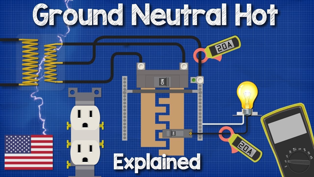
The Engineering Mindset explains the different roles of electrical conductors. This supports the interface-identification step; it is not a foot switch wiring diagram or a cable qualification procedure.
Watch Ground Neutral and Hot wires explained – The Engineering Mindset
Frequently asked questions
Can I use a guitar cable for an industrial foot switch?
Only if the equipment manufacturer explicitly approves that exact cable assembly and interface. Similar plugs or connector counts do not prove compatible wiring, function or electrical ratings.
How much extra cable should I order?
Determine it from the installed route, permitted pedal positions and a controlled service-slack arrangement. Obtain the actual bend and flex limits; there is no universal additional length for every workstation.
Does strain relief mean the cable is waterproof?
No. Pull retention and ingress protection are different properties. Confirm the jacket, entry and connector evidence separately for the actual exposure.
Is a continuity test enough after extending a lead?
No. Continuity can help identify an open connection, but it does not establish input voltage margin, insulation condition, noise behavior or the equipment response required for approval.