
Equipment power socket polarity means the intended line, neutral and protective conductor paths remain correctly identified through the cord, connector, inlet and internal assembly. Alternating current does not make those conductor roles interchangeable. Verify the exact connector drawing and equipment circuit before interpreting a photograph or performing a test. A connector that fits, a machine that powers on, or a three-light socket tester alone does not prove the complete assembly is correct. This guide focuses on equipment inlet identity and verification records, rather than household receptacle repair or a universal pin-position diagram.
The intended readers are equipment builders, procurement teams and competent maintenance personnel. Electrical inspection and testing must follow the actual equipment requirements and workplace procedures. The illustrated product is a visual reference, not a verified wiring assignment. Do not infer a terminal function from the location shown in an illustration.
Separate polarity from protective earthing
In a supply system that distinguishes line and neutral, polarity concerns the connection of those conductors to their intended points. Protective earth, when required by the equipment design, serves a different purpose. It is part of a protective path rather than a substitute return conductor. Do not connect neutral to an enclosure inside the equipment simply because both conductors may have an earth-related relationship elsewhere in a particular supply system.
The design determines how the inlet, protective devices and internal circuit relate. A correct inlet termination does not establish that the complete cord assembly or upstream installation is correct. Equally, a correct supply socket cannot compensate for a miswired internal harness. Review these as connected parts of one path, with each boundary clearly identified in the verification record.
For the protective-path design itself, use the separate equipment inlet grounding guide. This article instead addresses conductor identity, orientation and acceptance evidence. Keep those records distinct so that one successful check does not silently replace another required inspection.
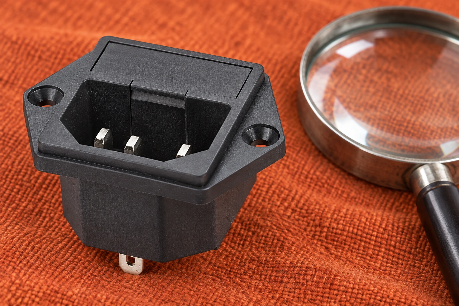
Resolve front and rear views before assigning terminals
A front view into an inlet and a rear view toward its terminals can reverse the apparent left and right positions. The drawing must state the viewing direction. Record whether it shows the mating face, the wiring side or a section. Also locate the keying features and mounting orientation. Rotating a photograph to fit a page can make a familiar connector look as if its terminal order has changed.
Use the exact order code and its approved drawing. A family photograph may show several mounting variants, while the purchased part has its own terminal construction and internal arrangement. Ask for a drawing that covers that variant. If the moulded identification is difficult to read, resolve it with the supplier rather than replacing it with an assumption from another brand’s diagram.
Make a simple terminal-to-function record with the drawing revision, view direction and inspection photograph. Have the responsible reviewer compare it with the schematic. This is particularly useful when purchasing and assembly teams work from different documents. A drawing is only useful if the assembly instruction uses the same reference points and describes the same orientation.
Trace the cord, inlet and harness as separate boundaries
Begin with the approved supply arrangement and list every connection between the supply interface and the equipment circuit. Include a detachable cord if present, its mating connector, the inlet and the internal harness. An adapter or substitute cord introduces another boundary that must be reviewed. Do not assume that physical mating proves correct conductor identity or suitability for the equipment’s destination market.
Conductor colour can support identification when the applicable requirements and assembly documents establish its meaning. It is not independent proof of the entire path. A coloured wire may be terminated incorrectly, a repaired cable may differ from the original, or a supplied assembly may use a different identification method. Check the actual point-to-point connections against the approved record.
When a fuse or switch is integrated into a power-entry assembly, use the specified internal circuit. The visible presence of a fuse drawer does not establish which conductor it interrupts or prove that the complete module has the intended circuit. Review the power-entry module comparison only as supporting context; obtain the exact module documentation before approval.
Build an inspection matrix instead of a generic wiring sketch
The following matrix identifies evidence to collect. It deliberately gives no universal blade assignment, conductor size or test threshold. Those values come from the actual component and equipment requirements. HSE’s guidance on maintaining portable electrical equipment includes inspection and testing considerations, including supply-cable polarity, and explains the need for competence when interpreting electrical tests.
| Boundary | Evidence needed | Reason to stop approval |
|---|---|---|
| Mating connector and inlet | Exact interface drawing, view direction and order code | Identity depends only on an unlabelled photograph |
| Supply cord | Approved cord specification and point-to-point conductor record | Substitution lacks an evaluated connection record |
| Internal harness | Schematic revision, termination instruction and inspection result | Harness orientation conflicts with the inlet drawing |
| Integrated fuse or switch | Variant-specific internal circuit and intended protective arrangement | Function is inferred from appearance alone |
| Finished equipment | Applicable verification method, results and responsible sign-off | A power-on check is the only acceptance evidence |
Attach the matrix to the assembly record rather than leaving it as a general checklist. Each entry should identify the specific evidence and its revision. Mark an unresolved item openly. A blank field is a pending decision, not an implied pass. This makes incoming inspection more useful and prevents an undocumented replacement from becoming the new production reference.
Plan isolated checks without creating a live-work shortcut
Define the intended checks before touching the assembly. Identify all energy sources and any stored energy, and use the approved isolation process. An off switch does not establish a safe condition. Competent personnel must verify the condition with suitable equipment and procedures before making resistance or continuity measurements. Disconnect enough of the path to prevent other circuit branches from misleading the result.
A point-to-point check can help confirm which disconnected conductor reaches which terminal. It does not by itself prove insulation quality, protective-path performance, load capacity or overall equipment compliance. Specify the actual test points and method in the work instruction. Where further tests are required, perform and document them under the approved verification plan rather than improvising from a continuity beep.
HSE’s safety in electrical testing guidance discusses managing testing risks and the limitations of simple plug-in socket testers. Keep the distinction between identifying a connection and approving electrical safety explicit. If a necessary check cannot be performed safely with the available competence and instruments, hold the assembly and escalate through the established review process.
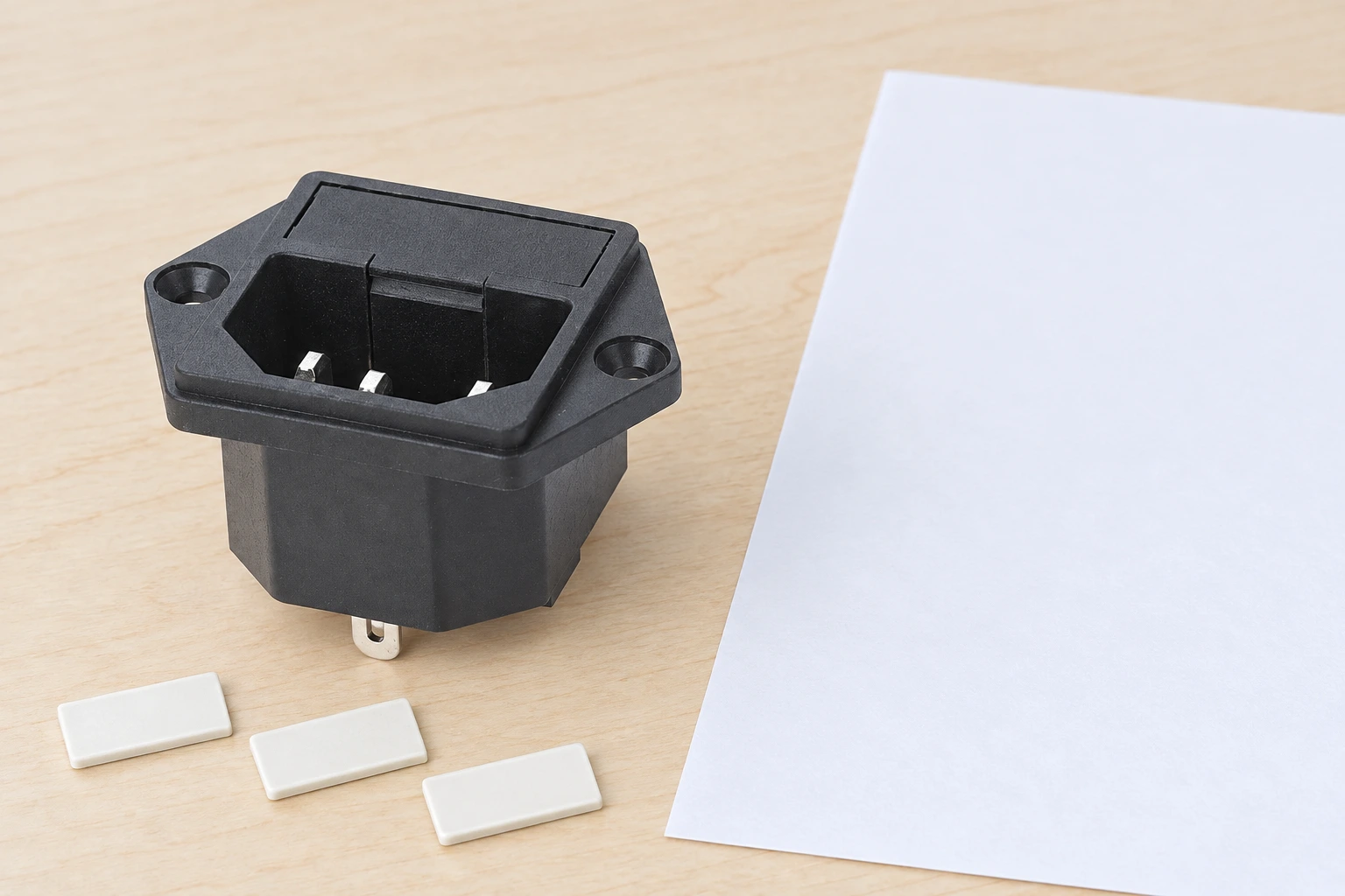
Interpret a successful power-on test cautiously
Many loads can operate despite an incorrect conductor connection. Normal operation therefore does not establish that a switch, protective device or accessible part relates to the supply as intended. The acceptance record should state which property each test proves and which properties remain outside its scope. Avoid the vague conclusion that the equipment is good simply because its indicator lights.
Similarly, a simple tester can provide limited information about a supply point without proving the entire equipment harness. Read the instrument instructions and know its limitations. Do not apply a tester intended for a particular supply interface to another assembly through an improvised adapter and treat the indication as conclusive. Document any necessary adapter as part of the approved test setup.
If results disagree with the drawing, stop and investigate the disagreement before energizing the equipment. Preserve the as-found condition with photographs and records. Check the viewing direction, conductor identification, substituted parts and measurement method. Do not move wires experimentally until the display looks familiar; that can hide the original cause and leave the equipment outside its approved configuration.
Control substitutions and supplier evidence
For a LEMA enquiry, identify the desired interface, mounting method and terminal process using the IPZ series equipment power socket as the product-family starting point. Request variant-specific drawings and documentation. This article does not assert a universal pin assignment, certification or market approval for every member of that family.
Agree who supplies and verifies the cord, inlet and harness. Require notice before changes to terminal form, internal switching, fuse arrangements or identification. Keep an approved sample and drawing together. When inspecting a replacement batch, compare the physical part with those records rather than accepting a similar-looking face as sufficient evidence.
Use the power socket failure-mode guide for separate investigations of loose contacts, heating or arcing. Those symptoms may coexist with an identity error but are different questions. A polarity correction does not automatically repair a damaged connection or establish that an overloaded contact is suitable.
Close the review with a traceable record
The finished record should identify the component codes, drawing and schematic revisions, actual orientation, point-to-point results, applicable additional tests and reviewer. Keep photographs that show the terminal side clearly. Record the assembly date and any approved substitution. This allows a later maintenance team to compare a replacement with a known configuration rather than reconstructing it from memory.
If uncertainty remains, separate the verified facts from the missing information. For example, a connector may match physically while its internal arrangement is still undocumented. Hold that decision and request the required evidence. Reliable polarity control comes from consistent identity across the complete supply path and a suitable verification process, not from a single colour, a familiar blade position or a successful startup.
Further learning
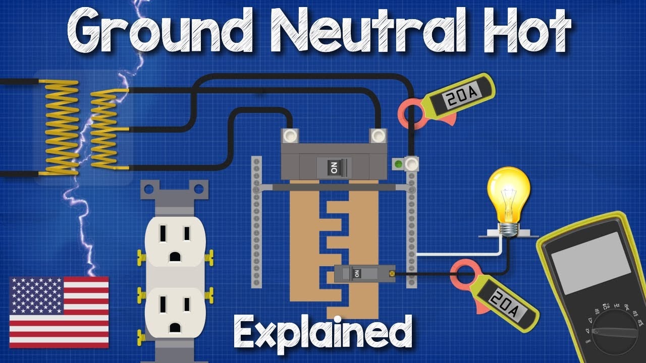
This independent educational video provides background for the checks discussed above. It does not identify the terminals of the illustrated LEMA product or replace the equipment manufacturer’s approved procedure.
Frequently asked questions
Does alternating current make line and neutral interchangeable?
No. In a system that distinguishes those conductors, their intended circuit roles still matter. Follow the approved equipment and supply-system documentation.
Can I identify terminals from a front-view product photograph?
A photograph alone is insufficient. Use the exact variant drawing, its viewing direction and the equipment schematic; resolve unreadable markings with the supplier.
Does a socket tester approve the complete equipment assembly?
No. Its indications have a defined scope and limitations. The cord, inlet, internal harness and required safety tests need their own approved verification.
Should neutral be connected to the enclosure inside the equipment?
Do not create that connection as a substitute for protective earth. Follow the equipment’s approved protection concept and supply-system requirements.