
An IEC inlet temperature rating is meaningful only when you know what temperature it describes. Maximum pin temperature, permitted ambient temperature and temperature rise are different quantities. A connector family associated with a higher pin temperature does not automatically approve an inlet for a hotter enclosure or a larger current. Identify the exact inlet, its mating connector and the applicable product documents, then review the thermal conditions of the complete equipment. This guide separates those checks so that buyers do not treat a housing photograph, a material description or a familiar connector name as thermal approval.
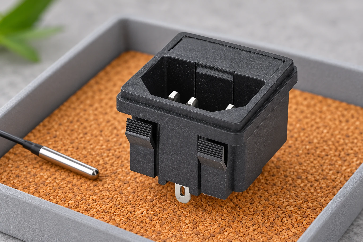
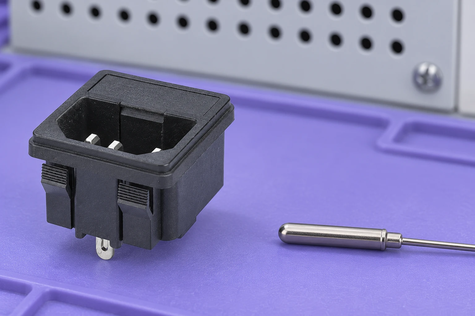
The intended readers are equipment designers, purchasing teams and qualified maintenance personnel. Illustrations use a real LEMA IPZ snap-in inlet as a visual reference. They do not establish its connector classification, temperature limit or certification. Electrical and thermal testing must follow a procedure defined for the actual equipment; this article does not provide universal acceptance limits.
Separate three temperatures before comparing products
Pin temperature concerns a specified part of the connection. Ambient temperature concerns the surrounding air under defined conditions. Temperature rise is the measured increase above the reference ambient during a defined test. A document may discuss all three, but a number from one category should never replace a missing number in another. Record the measurement location and condition with every temperature value.
Consider a hypothetical component described by a maximum pin temperature. That statement alone does not tell you its permitted local ambient, how much rise it develops at a particular current or whether nearby equipment can expose its plastic body to additional heat. Similarly, a housing material’s laboratory property is not a rating for the assembled inlet. Ask for the finished component data and the conditions under which it applies.
The IEC 60320-1:2021 catalogue entry identifies general appliance coupler requirements and describes an additional annex for couplers intended for higher ambient temperatures. That distinction is a reason to check ambient evidence separately. The catalogue summary is not the complete test procedure and does not approve a particular LEMA part.
Use connector temperature classes without overgeneralizing
IEC standard sheets distinguish mating interfaces and associated conditions. As a documented reference example, the 2014 IEC 60320-3 preview hosted by SIST presents C13/C14 with a maximum inlet pin temperature of 70°C, C15/C16 with 120°C and C15A/C16A with 155°C. These examples explain why similar-looking connectors are not interchangeable simply because their current designations appear alike.
Use the applicable edition and the actual product approval for a purchasing decision. The IEC consolidated Part 3 catalogue entry includes the later amendments and identifies the standard-sheet reference family. The older preview above is used to illustrate distinctions, not to declare that its entire table is the current assessment basis for every equipment project.
| Reference mating pair | Maximum inlet pin temperature in the cited 2014 preview | What still needs verification |
|---|---|---|
| C13 connector / C14 inlet | 70°C | Exact purchased variant, applicable approval and local thermal conditions |
| C15 connector / C16 inlet | 120°C | Correct keyed interface and documented compatibility of the complete cord assembly |
| C15A connector / C16A inlet | 155°C | Actual part documentation, installation conditions and equipment assessment |
The figures concern inlet pin temperature in that cited reference. They are not ambient-temperature permissions, target operating temperatures or claims about the illustrated IPZ inlet. Do not modify connector keying or assume that an apparently compatible cord is acceptable for a hot-condition inlet.
Identify heat entering from outside the connection
An inlet may sit near a power supply, heater, motor drive or warm internal airflow. Map those heat sources before selecting a component. The local air surrounding the inlet can differ from the room temperature used in a design brief. A compact enclosure can also warm after sustained operation, so an early measurement may miss the condition that matters.
Review the permitted installation arrangement: mounting panel, ventilation, orientation and nearby components. A metal panel, a plastic enclosure and an open bench fixture can transfer heat differently. Record the actual configuration used for assessment rather than treating one photograph as representative of all installations. If a supplier gives a temperature limit, ask where it is measured and what conditions apply.
Check the effect of the mating cord connector as well. It can cover part of the inlet, change airflow near the interface and introduce its own thermal limits. The cord’s insulation and termination construction have separate requirements. A higher pin-temperature class does not erase those limits or establish that an existing cord assembly can remain in use.
Separate load heating from a connection defect
Electrical resistance at a loaded connection contributes heat. The relationship P = I²R explains why current and resistance both matter, but it does not provide an allowable temperature. A loose or damaged interface may generate excessive local heat even when the equipment’s normal current is below a catalogue rating. Raising the connector temperature class is not a substitute for correcting a defective connection.
Look for changes in contact condition, mating retention and terminal assembly. Keep observations and measurements separate from conclusions. Discoloration, an odor or intermittent power can justify removing equipment from service under the approved procedure, but those symptoms alone do not identify the exact failure mechanism. Preserve evidence before replacing a part or cleaning a contact.
The inlet contact resistance guide discusses measurement and heat investigation. The power socket failure modes guide covers fault boundaries and quarantine records. This article instead helps define the thermal specification and the assembly conditions that should be reviewed before procurement.
Plan a representative thermal assessment
The responsible engineer should define the relevant operating modes, loading, environmental conditions and measurement locations. Include configurations that represent the equipment’s intended use, rather than selecting a light-load mode because it produces a comfortable result. State how the assessment deals with stabilized conditions or changing duty cycles. The procedure must come from the applicable requirements and product documentation.
Keep the equipment configuration with the measurements: inlet code, cord assembly, panel, ventilation, internal layout and load mode. Opening a cover for easier access can change the cooling condition. A suitable method must obtain the needed information without quietly converting the test into a different installation. Record any unavoidable differences and have the responsible reviewer judge their significance.
Measurement equipment also has limits. Sensor position, attachment method, thermal response and instrument uncertainty can influence results. A thermal image of a shiny metal surface is not automatically a reliable pin-temperature measurement. Use a method appropriate to the specified point and retain the setup record. Do not attach probes to energized equipment without the necessary competence and approved safeguards.
Choose the exact mounting and terminal variant
The LEMA IPZ product reference includes visibly different mounting constructions. The snap-in model illustrated here has retaining clips; the screw-mounted alternative uses a flange. Neither visible feature establishes a temperature rating. Ask for the drawing, material specification and rating evidence covering the precise part offered.
Check panel thickness, retention and harness space against that drawing. A crowded terminal area can complicate assembly and inspection, while poor retention can allow repeated movement at the mating interface. These observations belong in the component comparison. They are not a reason to improvise an installation method or substitute an unapproved terminal accessory.
For the electrical designation, use the complementary 10A versus 15A inlet approval guide. It addresses market-specific documents and the complete power path. Keep its current comparison separate from the thermal record: an ampere value and a pin-temperature class answer different questions, and both must fit the equipment configuration.
Write a supplier request that closes the gaps
Send the supplier a concise application record rather than asking only for a high-temperature inlet. Include the mating interface, destination markets, mounting construction, terminal version, anticipated local ambient and equipment operating modes. Ask for the maximum pin temperature, permitted ambient conditions, applicable approvals and installation restrictions for the exact proposed order code.
If the supplier provides a family brochure, request the page and revision covering the selected variant. If the answer mentions a plastic material temperature property, ask how that relates to the finished component assessment. Avoid accepting a general material number as proof of the entire inlet’s performance. A clear unanswered question is safer and more useful than an undocumented assumption.
Close the review with a traceable decision: approved part and cord combination, applicable documents, assessment conditions, results and reviewer. Repeat the relevant review when the enclosure layout, inlet variant, cord or duty cycle changes. A good temperature specification names the object, location and conditions behind the number; it does not merely choose the largest value in a connector chart.
Further learning
This independent educational video provides background for the checks discussed above. It does not identify the terminals of the illustrated LEMA product or replace the equipment manufacturer’s approved procedure.

Watch Electric power | Circuits | Physics | Khan Academy — Khan Academy Physics
Frequently asked questions
Is a 120°C pin rating also a 120°C ambient rating?
No. Pin temperature, ambient temperature and temperature rise describe different conditions. Verify each applicable limit for the exact component and equipment configuration.
Do the 70°C, 120°C and 155°C examples rate the pictured IPZ inlet?
No. They illustrate distinctions in the cited IEC standard-sheet preview. The pictured product requires its own exact-variant drawing, rating and approval evidence.
Can a hotter-rated inlet solve a loose connection?
No. A defective mating interface or termination requires investigation and correction. A higher temperature class does not establish that the connection is safe.
What should an OEM ask its inlet supplier?
Provide the interface, mounting, terminal variant, market and operating conditions. Request the corresponding pin-temperature, ambient, approval and installation documents for the exact order code.