
A micro switch temperature rise test evaluates heating in a defined loaded assembly relative to a defined ambient reference. It needs more than a warm-to-the-touch judgment or a single resistance reading. Establish the exact switch, terminal connection, conductor, enclosure, current duty and acceptance basis before testing. Record temperature over time until the method’s stabilization requirement is met, then compare both temperature rise and absolute temperature with the applicable limits. This guide helps OEM buyers prepare a representative test request without inventing a universal temperature limit for every micro switch.
Start with the decision the test must support
State whether the work is a development comparison, investigation of a field complaint, supplier qualification or a formal compliance evaluation. These purposes can require different specimens, methods and reports. A quick bench comparison can identify a suspicious connection, but it cannot automatically replace a prescribed product or equipment test. Agree who owns the test specification and who will approve the result.
Identify the full switch code and drawing revision. Add terminal type, mating connector, conductor material and size, connection process and any mounting hardware that influences the installation. A result obtained with one connection cannot simply be assigned to another arrangement. The heat source might be a contact path, a loose connector, a conductor or an external component near the switch.
The KW7 series page is a starting point for an inquiry about a physical switch family. The KW7 selection guide organizes the wider component review. Request the exact supported variant data and any applicable test conditions from Lemaele. Do not turn a family-level current marking or operating ambient statement into an assumed temperature-rise limit. The complete application must remain within the relevant component and equipment requirements.
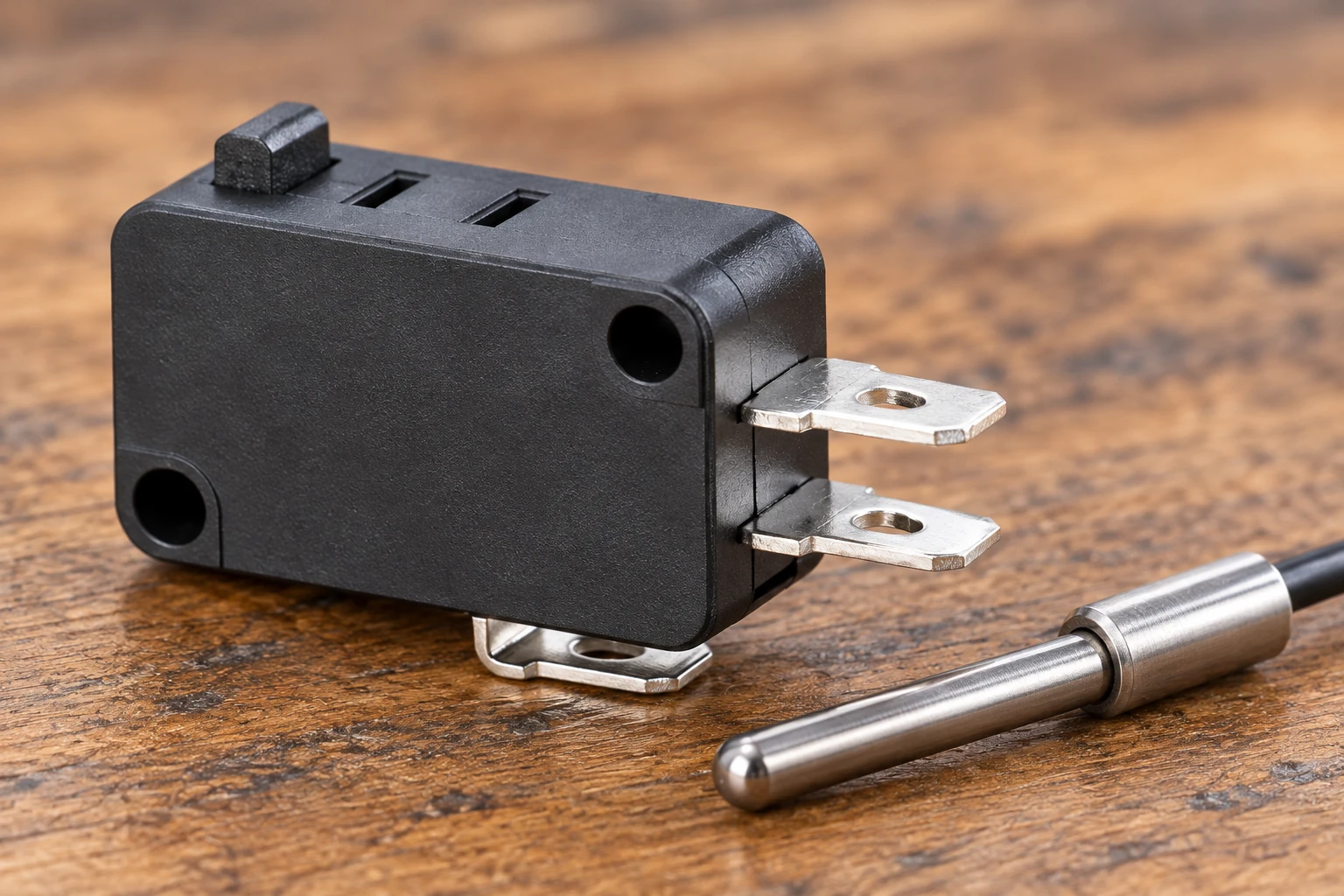
Distinguish temperature rise from absolute temperature
Temperature rise is the difference between a measured point temperature and the defined ambient reference at the corresponding time. As a hypothetical arithmetic example, a terminal at 57 degrees Celsius and an ambient reference at 27 degrees Celsius give a rise of 30 kelvins. These numbers are not a pass limit, a KW7 measurement or a recommended operating condition. Record both temperatures rather than keeping only their difference.
A temperature difference does not describe the whole operating condition. The same rise at a higher ambient produces a higher absolute point temperature, which may matter for adjacent materials and components. Confirm which limits apply to each point and which environmental conditions the specification requires. Do not extrapolate a convenient room-temperature result to a warmer enclosure without a supported assessment.
The chosen ambient sensor should represent the specified environment, not accidentally measure a local heat plume, a cold draft or contact with the enclosure wall. Define its placement in the method. If the assembly contains other heat sources, record their operating states. A test that leaves nearby equipment off may not represent the temperature environment of the installed switch.
Understand the electrical heating question
For an ideal resistive path carrying DC, dissipated power can be expressed as P = I squared R. Use amperes and ohms to obtain watts. The OpenStax discussion of electrical energy and power provides the basic relationship. It explains why current and resistance are relevant inputs; it does not predict the temperature of a complete switch assembly.
As an illustrative calculation, 4 A through a hypothetical 0.02 ohm path gives 0.32 W. Doubling that current while holding the resistance constant gives 1.28 W. These figures show the mathematical sensitivity only. Real resistance may change with condition and temperature, and the route by which heat leaves the assembly also matters. No permissible switch current is derived from this example.
Our contact resistance article covers the separate electrical measurement. A resistance result and a thermal result answer different questions. Use both where appropriate, with their test conditions recorded, but do not substitute one for the other. A localized poor terminal connection may also require inspection beyond the internal contact path.
Build a representative specimen and load
Use the intended conductor and mating terminal, prepared with the controlled production process. Record the tool, crimp or solder method where relevant, and the insertion condition. If you are comparing connection options, change one defined factor at a time and retain specimen identities. Otherwise, a cooler result might come from an unintended difference in wire length, fixture contact or airflow.
Include the enclosure, orientation, mounting and nearby heat sources required by the test specification. Conductors can carry heat away as well as carry current, so an arbitrary laboratory lead arrangement can affect the observation. Document conductor routing and exposed length instead of leaving them to an individual operator’s memory. Photograph the specimen as a record, not as a substitute for the written setup.
Specify the load waveform, current duty, switching state and supply conditions. A continuously closed contact under load is not the same evaluation as repeated electrical operation. If both are needed, define the relationship between the tests and the specimen sequence. Distinguish carrying-current heating from startup pulses and switching endurance. Qualified personnel should establish protection, safe access and shutdown conditions before energization.
| Control | Specify | Why it matters |
|---|---|---|
| Specimen | Complete switch and mating terminal codes | Tie results to an identifiable configuration |
| Conductors | Material size preparation and routing | Preserve electrical and thermal paths |
| Environment | Enclosure orientation and nearby heat sources | Represent installed cooling conditions |
| Load | Waveform current duty and operating state | Separate carrying from switching evaluation |
| Sensors | Point channel attachment and calibration | Describe what temperature was measured |
| Endpoint | Method-defined stabilization and limits | Avoid unrelated duration or pass criteria |
Select sensors and installation methods deliberately
Identify the measurement points before placing sensors. Examples may include a terminal connection, an accessible housing location and an ambient reference, depending on the governing method. An external housing measurement cannot automatically be reported as the internal contact temperature. State exactly what was measured and avoid a more specific claim than the sensor placement supports.
Sensor attachment can alter the surface or heat flow being measured. NIST research on surface temperature measurement errors discusses the influence of heat exchange and thermal resistances in its own measurement context. The practical lesson is to evaluate the attachment and measurement uncertainty; the paper’s experimental conditions or numerical uncertainties must not be transferred directly to a switch test.
Record sensor type, channel identity, calibration information, attachment method and data acquisition settings. For infrared measurements, the method must also address surface emissivity and reflections. Shiny terminal metal and black housing should not be assumed to behave identically in a thermal image. Use the responsible laboratory’s validated approach rather than selecting a display setting simply because the image looks plausible.
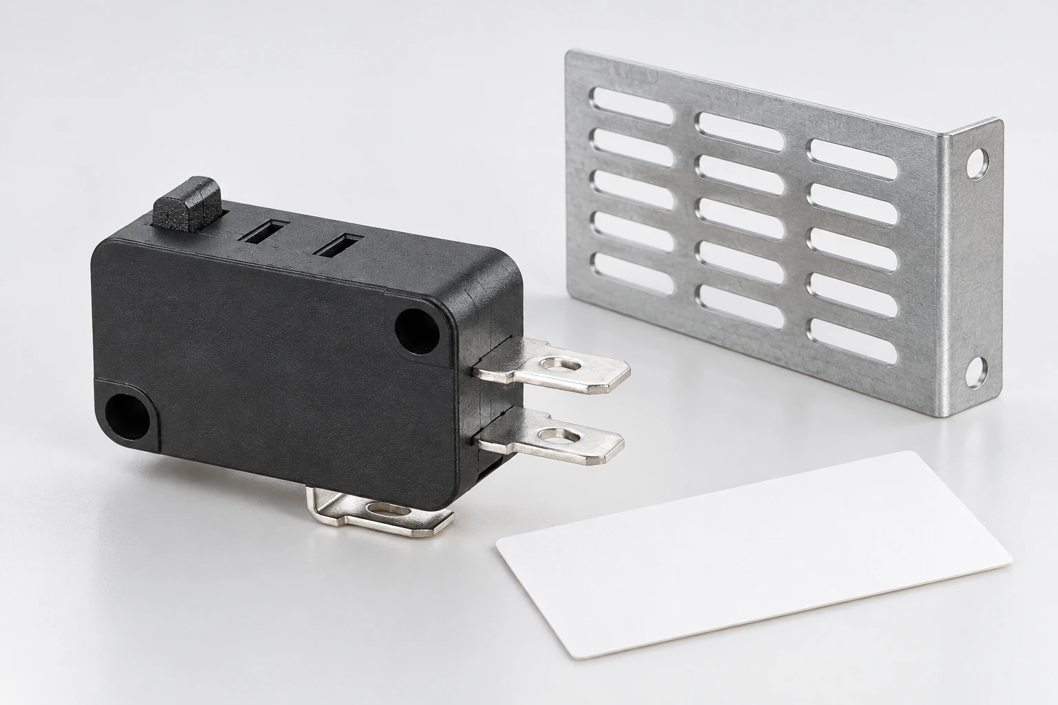
Observe the full temperature history
Begin with a recorded initial condition and capture temperatures, ambient reference and load information over time. Use the stabilization definition required by the agreed method. Do not adopt a fixed duration or a rate-of-change criterion from an unrelated switchgear, transformer or connector article. Similar terminology does not establish that two standards or product tests are interchangeable.
Review the time traces before reducing them to a table of final values. Look for unexpected steps, drifting ambient, load interruptions or a sensor that may have moved. An apparently stable difference can hide a changing absolute temperature if the environment is also warming. Preserve the raw data and annotate meaningful events so an independent reviewer can reconstruct what happened.
If abnormal heating, damage or unstable behavior appears, apply the predetermined safe stopping procedure and investigate. Do not keep an unsafe specimen energized merely to reach a scheduled endpoint. Preserve the assembly condition for examination where safe, and record any changes made before a retest. A rerun after replacing a connector is a new configuration, not evidence that the original result never occurred.
Evaluate against an agreed acceptance basis
List the applicable requirement for every reported point and the source of that requirement. Distinguish a maximum operating ambient, material temperature boundary, specified temperature rise and equipment-level condition. If the necessary acceptance value is unavailable, the proper outcome is an unresolved decision. A visually intact part or a temperature that feels comfortable is not an alternative acceptance standard.
Include measurement uncertainty where needed for the decision, especially when the result is close to a limit. Describe the actual evaluated configuration and any exclusions. A result for one sample and one mounting condition should not be generalized to every member of a product family. Confirm the sampling and retest rules with the responsible engineer or laboratory before qualification.
After cooling and safe isolation, carry out the inspections and electrical checks specified by the method. The incoming inspection guide can help organize identity and evidence records, while the terminal strength article addresses a separate mechanical boundary. Do not call a thermal test a complete electrical, mechanical or endurance qualification.
Prepare the supplier review package
Send the exact switch and terminal codes, application drawing, load data, conductor specification, enclosure description and proposed measurement points. Include the intended ambient range, duty, acceptance source and reporting format. Ask Lemaele to identify relevant product evidence and any limits on applying existing results to your assembly. Mark unknown inputs clearly instead of allowing them to become hidden assumptions.
Retain the final report with specimen identities, configuration photographs, raw time records, instrumentation details and the release decision. Review its applicability when a connector, conductor, enclosure or load changes. This makes a temperature rise test useful to purchasing and production: the result remains tied to the assembly that was actually evaluated, rather than becoming an unqualified claim that the switch does not get hot.
Learn temperature measurement principles
nptelhrd: Lecture – 4 Temperature Measurement. NPTEL explains temperature measurement principles. It supports selecting and interpreting instrumentation; it is not a KW7 thermal qualification procedure or product temperature limit.

Watch Lecture – 4 Temperature Measurement.
Frequently asked questions
Is ambient rating a temperature-rise limit?
No. They describe different quantities. Obtain the applicable point limits and test conditions for the component and equipment, and retain both absolute temperatures and temperature differences.
Can I judge the result by touching the housing?
No. Touch is not a controlled measurement and may be unsafe. Use qualified personnel, suitable instruments and the approved test method with defined measurement points and acceptance criteria.
Does a thermal camera measure internal contact temperature?
Not directly from an external housing image. State the surface actually observed and account for the method, including emissivity and reflections where relevant. Do not claim an inaccessible internal temperature without supporting evidence.
How long should the test run?
Use the stabilization requirement and duration specified by the governing method. A time or rate copied from a different product test does not establish the correct endpoint for this assembly.