
Limit switch mounting witness marks provide a visual reference for later inspection, but their alignment does not measure bolt tension, prove the original tightening operation or verify switching performance. Treat a changed mark as a reason to investigate under an approved procedure, and an unchanged mark as only one observation. A useful record identifies which parts the mark spans, when it was applied and what installation condition was accepted at that time. Without that baseline, a neat stripe can be easy to see while providing little dependable information about the switch’s installed condition.
Decide what the mark is intended to reveal
A limit-switch assembly contains several relationships that can change independently: the switch body relative to its bracket, the bracket relative to the machine, and an adjustable actuator relative to the switching head. A stripe spanning one relationship does not monitor all the others. Identify the actual joint and the movement that matters before deciding where an inspection reference belongs.
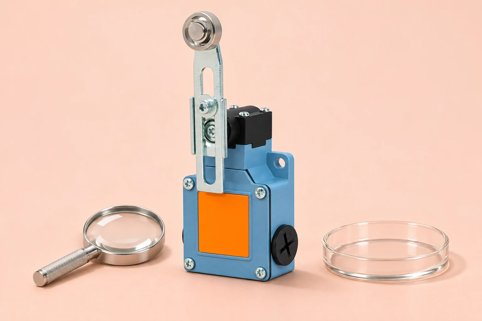
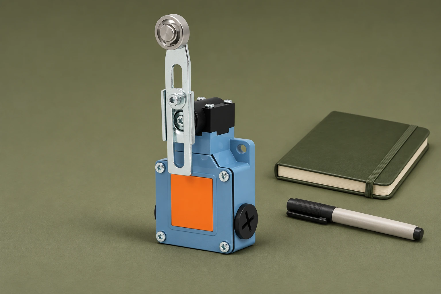
For the LZ1 series limit switch, obtain the drawing and instructions for the exact actuator, mounting arrangement and hardware. The product photograph is useful for identifying visible construction, but does not establish a permitted marking surface, chemical compatibility or tightening procedure. Those questions need applicable documentation and approval for the installed machine.
The mounting position and repeatability guide covers the functional relationship between switch and target. Witness marking is a supporting inspection method within that arrangement. It should not become the sole acceptance criterion for an installation whose actual purpose is to operate and release at the required machine positions.
Establish the installation baseline first
Make the equipment safe before inspection or work near moving parts. Follow the approved energy-isolation procedure and any additional requirements for stored energy, access and testing. A controller indication or an actuated limit switch is not a substitute for isolation. Define separately how any necessary energized functional verification will be conducted safely by competent personnel.
Before applying a mark, identify the assembly instruction, hardware and accepted installation condition. Record the switch orientation, target approach and relevant bracket position. If a torque-controlled assembly procedure applies, record the prescribed method and actual completion evidence. Do not apply a stripe to make an undocumented or suspect joint appear finished.
NASA’s mechanisms standard, revision B discusses inspection and torque striping in the context of mechanism verification. It is an aerospace reference, not a LEMA installation specification. The practical distinction is to retain the verification record that a visual reference supports, rather than allowing the stripe to stand in for an unrecorded assembly operation.
Choose reference surfaces deliberately
A line across a fastener and an adjacent surface can show their relative visible relationship. If the adjacent surface is a washer that can move, decide whether that is the intended reference. A mark spanning two movable pieces may remain aligned even while the wider assembly shifts. Explain the chosen reference in a photograph and inspection note so the next person knows what it represents.
Consider visibility and access under the actual maintenance conditions. A mark hidden by a guard, cable or accumulated contamination may not provide a practical inspection reference. Avoid placing it where it obscures identification, enters a moving mechanism or compromises a sealing or contact surface. The approved method must address the location and the product used, not just the color of a line.
Do not infer marker compatibility from its use on another machine. The solvent, binder, preparation and removal method may matter for coatings, plastics, seals and labels. Obtain approval where those materials could be affected. This article does not identify an approved marker for LZ1 or establish that an illustrated surface may be painted.
Record observations with an explicit next action
The following table is an inspection aid. It defines no universal acceptance limit, service interval or tightening instruction. Use the equipment’s approved maintenance and engineering process to determine whether a finding requires a hold, adjustment, replacement or further functional investigation.
| Observation | Preserve this evidence | Required decision boundary |
|---|---|---|
| Aligned mark | Baseline identity and current photograph | Does not measure retained clamp force |
| Displaced or cracked mark | Undisturbed close and context views | Investigate before renewing the reference |
| Missing mark | Maintenance history and surface condition | Do not assume either movement or acceptability |
| Shifted setup reference | Body, bracket and target relationship | Verify the approved operating position |
| Renewed mark | Authorized work and accepted new baseline | Retire the previous configuration explicitly |
Keep the words observed, suspected and verified distinct. A cracked stripe is an observation. Fastener rotation is one possible explanation, but the stripe material or inspection history may need review too. An unchanged stripe can be documented without converting it into a claim that preload remains adequate. This keeps the inspection record useful even when the condition requires additional assessment.
Photograph the mark before touching the hardware. Retain enough surrounding detail to identify the joint, while using a closer view to show the stripe itself. Record the inspection date, machine state and any previous maintenance that could have disturbed the reference. Where comparison photographs differ in angle or lighting, avoid inventing a precise movement measurement from an unsuitable image pair.
Why alignment does not prove clamp load
Clamp load is a mechanical state; a painted line is a visible relationship. They are not the same measurement. A joint can require engineering review for reasons that a stripe does not resolve, including the accepted assembly condition, settling of the joint or a changed interface. Use the original installation requirements and the relevant inspection method to assess the actual question.
NASA’s threaded fastener installation process specification distinguishes the effort required to turn an unseated locking feature from the torque associated with tightening. It illustrates why the meaning of a torque record depends on the process. Do not treat either an unspecified wrench reading or a visible stripe as a direct measurement of retained clamp force.
Avoid an informal re-torque check solely to see whether the stripe moves. Applying a tool changes the joint and can erase the original observation. If a torque audit, removal or reinstallation is required, follow the approved method and record the condition before and after. This article supplies no breakaway-torque criterion and no instruction to tighten an installed LZ1 mounting screw by a generic value.
Distinguish a mounting mark from an adjustment reference
A reference across a mounting screw concerns a different relationship from a setup mark locating a switch body on a slotted bracket. An actuator-position reference is different again. Name them separately in the maintenance record. Otherwise an inspector may report all marks aligned while checking only the fastener stripe and overlooking a shifted bracket or changed actuator setting.
Record what establishes the operating point: approved machine datum, target position, switch adjustment or another controlled reference. After an adjustment, verify operation and release through the required travel before accepting a new baseline. A line copied from the old position cannot establish that the old position was correct, especially when the machine arrived with an unresolved fault.
For a replacement assembly, use the limit switch replacement guide to address identity and the functional setup. Preserve the old photographs as history rather than making a replacement’s new marks look continuous with an unverified earlier condition. State which verification authorizes the new reference and when it took effect.
Investigate a changed or missing mark without concealing it
A changed stripe should trigger the defined inspection response. Record whether the line is displaced, broken, missing, covered or difficult to compare. These descriptions are more useful than writing loose bolt without checking the actual joint. Consider who last worked on the assembly and whether the reference was intentionally renewed, accidentally damaged or never documented.
Do not simply paint over a questionable mark and return the equipment to service. Determine whether the installation and functional conditions remain acceptable. If the joint must be disturbed, retain the before-condition record, perform the authorized work and document the new accepted baseline. A renewed stripe should be traceable to that work rather than silently replacing the evidence.
A missing mark also needs context. It may reflect an omitted maintenance step, removal during cleaning, a replaced component or a surface on which the chosen product did not remain readable. Establish the cause and the appropriate response. Adding more paint does not correct a poor marking method, and a more durable material still needs compatibility and process approval.
Keep functional verification alongside visual inspection
Observe the switch and target relationship through the approved check. Verify operation, release and the equipment response that the switch is intended to support. A mounting assembly can appear unchanged while the target, actuator or electrical path has a separate problem. Conversely, a functional signal observed once does not settle every question raised by damaged hardware or a changed mounting reference.
Include cable routing, access and surrounding mechanical conditions when they are relevant to the observation. Avoid altering those items as an unrecorded side task during inspection. The limit switch accessories guide can help identify related interfaces, while the actual machine documentation determines which checks and replacement parts are applicable.
If an application depends on a safety-related function, use the required system validation process and qualified personnel. A general limit-switch family description, ingress rating or inspection stripe does not establish a safety function for the complete machine. Maintain that boundary in purchasing and maintenance records so a convenient inspection aid does not acquire an unsupported role.
Build a usable handover and purchasing record
The handover should connect the component identity, joint location, installation instruction, verification result and baseline image. Add the marking method, approved material where applicable and the condition requiring escalation. Store the record where maintenance personnel can find it at the equipment, rather than relying on someone remembering why a particular screw has a stripe.
For supplier questions, provide the exact LZ1 variant and mounting arrangement. Ask for the applicable hardware and assembly guidance, and identify any proposed marking location requiring material-compatibility confirmation. Keep the request separate from unsupported claims that a mark proves the product cannot move. The useful deliverable is an agreed inspection reference within a verified installation.
When the assembly changes, retire the previous baseline explicitly. Include the replacement component, altered bracket or revised instruction in the new record. This gives future inspectors a reliable comparison and prevents a photograph from an earlier configuration being used as the acceptance reference for a different installation.
Further learning: preloaded bolted joints
The Ansys Learning lesson below introduces preloaded bolted joint design. It helps explain why joint loading is a mechanical subject distinct from visual stripe alignment. It is educational background, not an LZ1 mounting instruction, marker approval or numerical acceptance criterion.
Ansys Learning: Intro to Preloaded Bolted Joint Design — Lesson 1
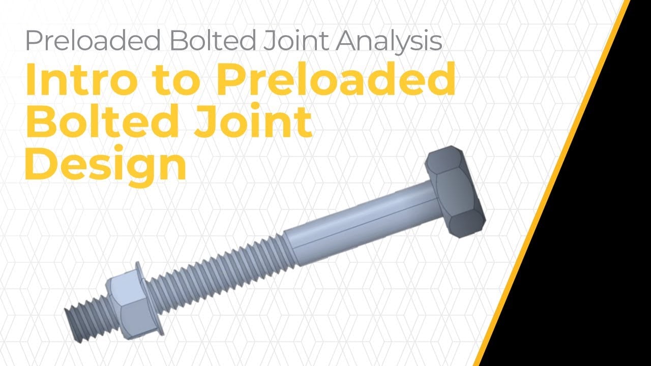
Watch Intro to Preloaded Bolted Joint Design — Lesson 1.
Frequently asked questions
Does an aligned stripe prove correct clamp load?
No. It records a visible relationship, not bolt tension or a complete joint assessment.
Should a cracked stripe simply be painted over?
No. Preserve the observation and follow the approved investigation and release procedure.
Can any marker be applied to an LZ1 housing?
No compatibility approval is established here. Confirm the material, location and method where needed.
Does a witness mark verify switch operation?
No. Verify operation, release and the required equipment response separately.