
Limit switch mounting hole elongation is a loss or change of mounting-hole geometry that needs investigation before a switch is repositioned or tightened again. First establish whether the opening is an intentional slot, an original clearance hole, or a feature that has changed in service. Preserve the undisturbed mounting evidence, compare it with the approved drawing, and assess both the support and the switch. A new switch cannot restore a worn bracket. This guide explains how to organize that review without inventing a universal hole-wear allowance or treating a successful electrical click as proof of a sound installation.
Identify which opening has changed
A limit switch can be attached to an intermediate bracket that is itself fixed to the machine. The actuator may also contain an intentional adjustment slot. These openings have different functions. Begin with a context photograph that identifies the switch, bracket, machine structure and target. Then identify the particular hole under investigation. An elongated opening in a bracket is not automatically damage to the switch enclosure, and a visible slot in a lever is not evidence of worn mounting.
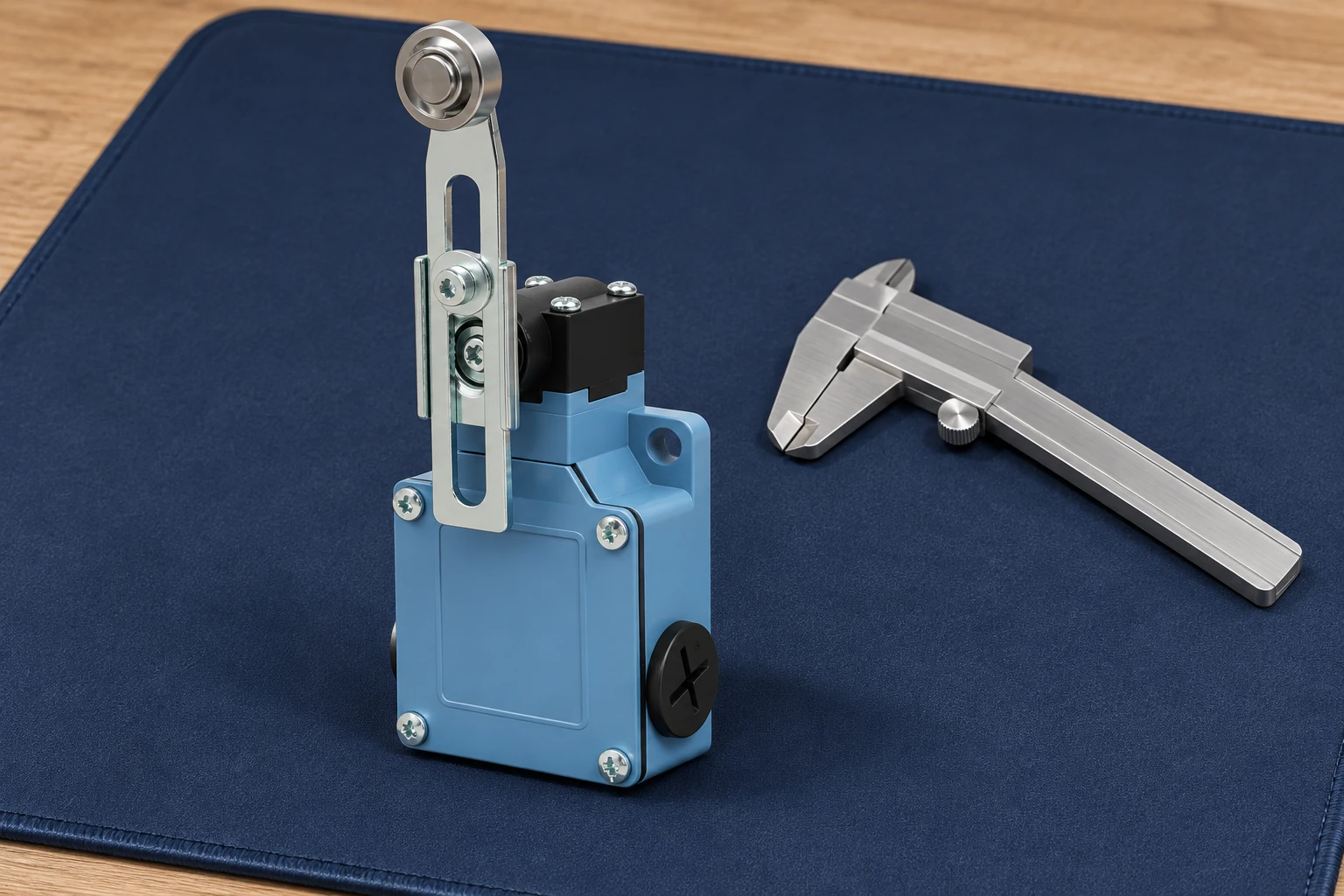
The LZ1 limit switch family provides the product context for this inspection. Its published family information does not establish the permissible wear of a customer’s mounting plate. Confirm the ordered variant, drawing revision and installation instructions before comparing dimensions. The illustrations show an intact reference product, not a damaged specimen or a repair instruction. Review the mounting position and repeatability guide separately for the relationship between the target and the installed actuator.
Make the inspection safe before disturbing the joint
Stop the equipment through its approved procedure, control hazardous energy and secure components that could move when the switch or bracket is released. A command at a control panel is not a substitute for the required isolation. Establish who may remove the assembly and what evidence must be recorded first. The HSE maintenance guidance explains why maintenance requires planning, competent personnel and measures against unexpected movement or energy release. Its guidance is general; follow the applicable equipment procedure and local requirements.
Do not demonstrate looseness by pushing a live mechanism toward a moving cam. If the reported symptom occurs only during production, preserve the existing operating record and arrange an approved investigation method. Note whether the complaint followed an impact, a relocation, a bracket replacement or repeated adjustments. This sequence can guide inspection, but timing alone does not establish the cause of the opening’s shape.
Preserve the original shape and contact evidence
Before loosening fasteners, photograph the opening and surrounding joint from useful directions. Record which side faces the machine and which faces the switch. Retain existing drawings, original commissioning photographs and previous inspection records. These can help distinguish an intended slotted design from a hole that became oval later. If the initial geometry cannot be established, record that uncertainty instead of labeling the feature as proven wear.
Observe visible edge damage, displaced material, local polishing, coating loss, cracks and the relationship of any washer to the opening. These are investigation leads rather than separate proofs of a particular mechanism. A washer may hide part of the edge. An undisturbed photograph may show the present position without revealing the full bore. If disassembly is authorized, preserve the fasteners and washers with their locations identified, and document what becomes visible only after separation.
Avoid filing, drilling, sanding or dressing the edge to make measurement easier. Those actions can remove evidence and alter the installation. Cleaning also needs an agreed method compatible with the materials and the investigation. Separate a finding observed before cleaning from one observed afterward. Do not interpret a cleaned surface as though it were the undisturbed condition in service.
Measure against a defined drawing and datum
An inspector needs to know which dimensions matter and which drawing applies. Record the hole’s orientation, location relative to a stable datum, and the instrument and method used. Where appropriate, measure in the suspected direction of elongation and across it. This is a way to describe geometry, not an acceptance formula. Surface coatings, burrs, access restrictions and irregular edges may limit what a simple caliper reading represents. The responsible reviewer should decide whether a different examination is required.
Do not compare only the largest dimension with a generic fastener diameter. The approved design may specify a clearance, slot, locating feature, washer arrangement or another detail that changes the interpretation. Likewise, two dimensions that look equal do not by themselves exclude edge cracking or loss of location. Preserve both the measurement and its limitations. If the drawing is missing, obtain the design basis before deciding whether to reuse the support.
Use a finding-to-decision record
The following table is a qualitative inspection aid. It contains no allowable ovality, tightening value, inspection interval or repair size. The HSE inspection guidance supports selecting checks according to installation conditions, deterioration risk and manufacturer recommendations. The specific observations and questions below help apply that approach to this mounting interface; they are not a replacement for the equipment’s engineering decision.
| Finding | Record before alteration | Question for disposition |
|---|---|---|
| Oval-looking opening | Drawing, orientation and original baseline | Intentional slot or changed geometry? |
| Exposed edge damage | Context and close photographs | What examination and hold are required? |
| Washer hiding the edge | Original arrangement and authorized removal sequence | What becomes visible after separation? |
| Apparent body movement | Each joint and its machine datum | Which interface actually moves? |
| Missing design limits | Exact drawing and supplier questions | Who can approve reuse or replacement? |
| Correction completed | As-built arrangement and functional checks | What supports release and later comparison? |
Separate hole wear from movement elsewhere
A switch that appears to move may have movement at the body-to-bracket joint, the bracket-to-machine joint, the adjustable head or the actuator attachment. Record those interfaces independently. Otherwise, a worn bracket hole may be blamed for a movement that starts elsewhere, or a new switch may mask a mounting problem temporarily. Keep the machine datum separate from the switch body when reviewing operating position.
The mounting witness-mark article addresses a different question: what a changed visual reference can reveal. A mark does not measure hole geometry or retained clamp force. For this review, keep a changed mark as one observation alongside dimensions, surface condition and installation history. Renewing a stripe is not a disposition for the underlying joint.
Also check the target relationship within the authorized investigation. A bent support, misaligned target or repeated impact may coexist with hole deterioration. Finding both does not prove which came first. Establish the sequence from service records where possible and avoid using the switch body as a mechanical stop. Any proposed change to the target path, locating arrangement or support stiffness belongs in the equipment design review.
Compare two plausible inspection outcomes
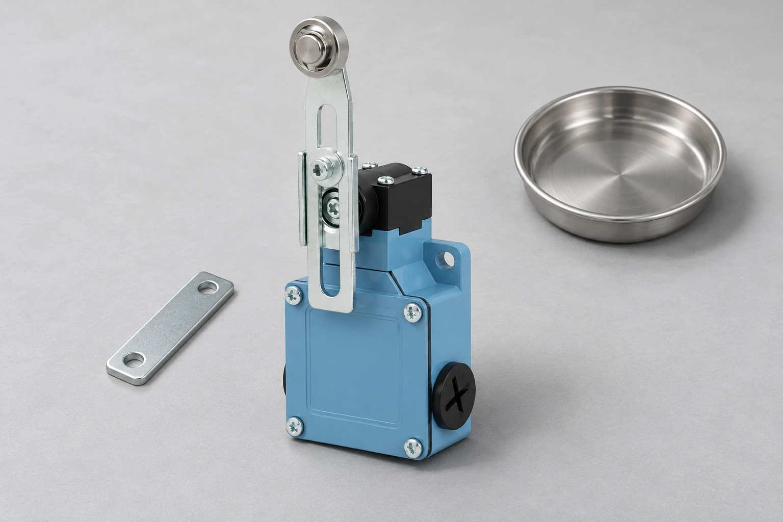
Consider an illustrative machine with a switch that has gradually shifted toward the edge of its adjustment range. The bracket drawing shows an intentional slot in one location and a round locating hole in another. A photograph of the slot cannot demonstrate deterioration. The inspector first identifies the actual feature, compares the locating hole with its drawing, and records the support condition without moving the assembly. No wear dimension or pass result is assumed in this example.
In one possible outcome, the round hole has changed geometry and the reviewer requires the bracket to be replaced. Installing a new switch alone would leave the changed support in place. In another outcome, the apparent oval shape matches the original slot and the actual problem is a different joint. The investigation then follows that finding. Both outcomes require evidence; neither can be selected from the symptom of shifting position alone.
The point is to avoid turning an adjustment into a repair decision. Moving the switch back to an old mark may restore an input at one position while leaving the reason for movement unresolved. Preserve the distinction between current electrical operation, mechanical support condition and the approved final arrangement.
Obtain a disposition before changing hardware
Send the reviewer the exact switch identity, bracket drawing, installation photographs, feature measurements, history and any relevant damaged parts. Ask whether the affected item is the switch, its mounting support or both. Ask what replacement or approved repair is permitted and which final checks are required. Do not assume that a larger washer, larger bolt, bushing, welded fill or newly drilled hole is acceptable merely because it covers the opening.
For purchasing, distinguish a like-for-like switch replacement from a mounting redesign. The industrial limit switch replacement guide covers identity and installed function; this inspection record should accompany it when the support is suspect. A substitute product with similar front dimensions may use different fixing or locating arrangements. Obtain the exact drawing instead of transferring assumptions from another enclosure or family.
Where the final decision replaces only the bracket, document that boundary. Where both switch and support are replaced, retain the reason for each. This helps future inspections identify whether a recurring problem belongs to the part, the mounting design or the way the machine is used, rather than accumulating unexplained replacement orders.
Verify the accepted assembly and retain the baseline
After an authorized correction, verify the final support and locating arrangement before returning to service. The equipment procedure should cover installation, target clearance, operating and release positions, cable effects and the required machine response. A continuity observation on a detached switch cannot verify those relationships. Record the accepted configuration, who released it, and which checks support that release.
Set later inspection according to the actual risk, exposure and findings. Do not copy an arbitrary cycle count or annual interval into the record. Compare subsequent observations with this accepted baseline, and review the interval if deterioration recurs. A useful closure explains what changed, why the disposition was appropriate and what evidence the next inspector should compare.
Safety background video
Work Safe Queensland: Isolating machinery when not in production

Watch Isolating machinery when not in production.
Work Safe Queensland explains machinery isolation during non-production periods. It supports the planning of safe access for the inspection discussed here. It does not demonstrate an LZ1 mounting test, specify a hole-wear allowance or authorize any bracket repair.
Frequently asked questions
Does an elongated-looking hole always mean wear?
No. First compare the exact feature with its approved drawing; it may be an intentional slot.
Can a larger washer make a worn bracket acceptable?
Do not assume so. Obtain a documented disposition for the support and the complete joint.
Will a new limit switch fix an elongated bracket hole?
A new switch does not restore the geometry of a separate worn bracket. Review each affected part.
Does electrical operation prove the mounting is sound?
No. Electrical operation and the mechanical condition of the installed support require separate evidence.