
A micro switch for elevator-door equipment can report a defined mechanical state to the door or lift controller. It is not automatically a complete door lock and cannot replace the applicable elevator safety design. Select it from the mechanism travel, safe contact logic, mounting, electrical interface, and system validation plan.
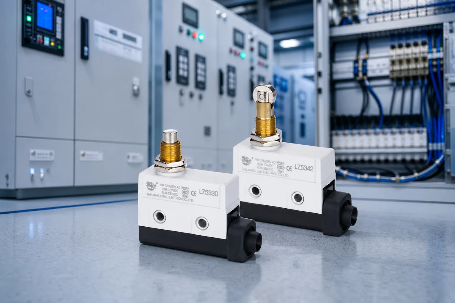
Part 1. What does a micro switch do in elevator-door equipment?
A micro switch changes its contact state when a lever, cam, key, roller, or plunger reaches a defined position. In elevator-door equipment, that state can be used as one input that indicates a door, panel, linkage, or lock-related mechanism has reached its intended mechanical position. The controller and complete door system determine what action follows from that state.
Start with the function, not the phrase “elevator switch.” Record the state to be detected, the required state if the actuator is released, the downstream controller response, and what fault must be detected. A position report, a door-closed indication, and a complete locking function have different responsibilities.
| Question | Design input | Risk if omitted |
|---|---|---|
| What moved? | Door, latch, cam, roller, or linkage | Wrong actuator or mounting choice |
| Which state is safe? | NO, NC, or changeover logic | Incorrect fault behavior |
| Who acts on the state? | Door controller or approved interlock system | Unclear circuit ownership |
| How is it proven? | Installed-module validation | Nuisance stops or missed states |
The LEMA Limit Switch product line is a category-level starting point. A quotation still needs the actual mechanism and controller inputs.
Part 2. How is a position switch different from a complete door lock?
Elevator codes address door locking devices and closed-detection means. A complete door-lock assembly can include a mechanical retaining function, key engagement, contacts, and controller wiring. A micro switch can be an element in that arrangement, but it is not enough evidence to label a generic component as a compliant locking device.
Keep the scope clear during sourcing. The integrator owns the complete safety architecture, code interpretation, wiring method, and validation. The component inquiry should describe the precise mechanical state that needs sensing and the electrical interface supplied by the controller.
- Position sensing: reports travel or a reached state.
- Closed detection: provides one defined input after door movement.
- Locking assembly: retains or verifies a lock function as part of a complete approved design.
- Service access: follows the lift equipment’s documented maintenance procedure.
For a broader actuator comparison, see roller actuator selection. It does not replace the door-system design review.
Part 3. Which travel and actuator inputs matter?
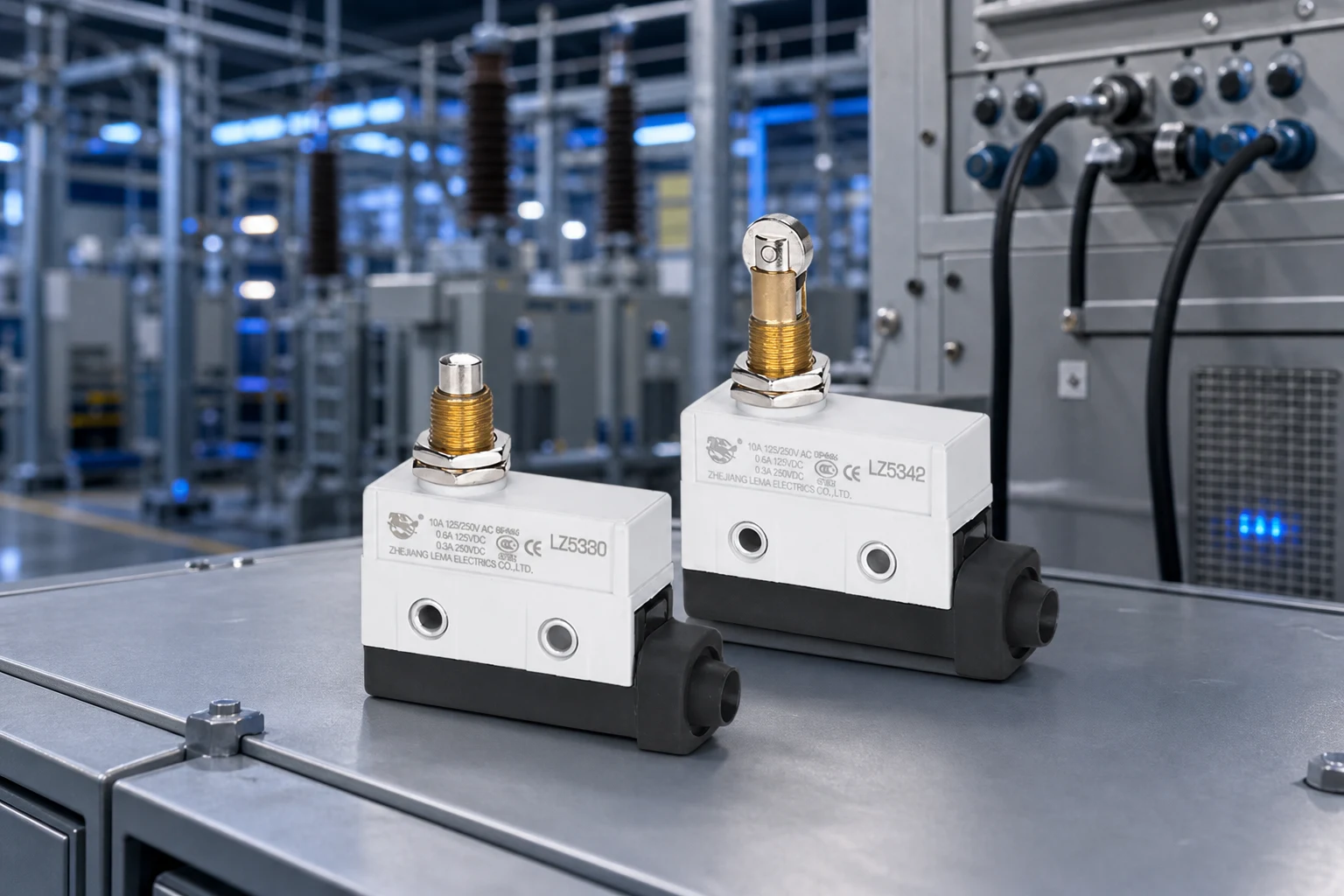
Mechanical margin is the first reliability check. The installed mechanism must cross the operating point at all production tolerances, and it must release cleanly when the door moves back. A nominal CAD position alone is not enough because brackets, rollers, fasteners, panel alignment, wear, and thermal movement change the real actuator path.
| Mechanical field | Review question | Typical failure |
|---|---|---|
| Operating travel | Does every unit reach contact transfer? | Intermittent door state |
| Overtravel | Is post-transfer force controlled? | Actuator damage or drift |
| Release travel | Does the signal reset with actual door movement? | Stuck closed/open indication |
| Mounting datum | Are controlled surfaces used? | Build-to-build variation |
| Load direction | Does the cam push as intended? | Wear and false states |
Provide the movement drawing, not just a switch photograph. It should show free position, target position, travel window, actuator direction, interference limits, and cable or terminal clearance.
Part 4. How do teams prevent false door-open states?
Repeated door-open faults often start at the interface: a loose bracket, worn cam, bent lever, poor alignment, insufficient overtravel, connector movement, or harness force can leave the switch close to its transfer point. The resulting intermittent input can look like a controller problem even when the mechanical source is upstream.
Check the final assembly at nominal and tolerance-limit positions. Cycle the door through closing, opening, vibration, and service access. Observe the input at the controller, not only continuity at a loose component. Record the approved adjustment and maintenance method so technicians do not create an uncontrolled bypass.
- Control the mounting datum and fastener retention.
- Keep the harness from loading the terminal or actuator.
- Use the specified actuator direction and travel margin.
- Review connector retention and environmental contamination paths.
- Escalate recurring faults to the door-system owner.
Part 5. Which electrical interface belongs in the control plan?
Define the contact form from the actual safe-state logic. A controller may require normally open, normally closed, or changeover behavior, and the selected circuit can have different needs from any power or locking circuit. Record voltage, current, load type, input conditioning, terminals, connector, wire routing, and fault response.
Do not infer a safety-circuit rating from an article or a family name. The final model must be checked against its quoted documentation and the integrator’s circuit design. The separate door and controller input boundary article illustrates why physical door state and complete system behavior must stay separate.
Part 6. What must be validated before release?
Validation should use the production-intent door, bracket, actuator, wiring, controller input, and service method. Test state changes across travel extremes and after the conditions the door system is expected to see. The component supplier’s data is an input to this work, not a replacement for the integrator’s verification.
RFQ input checklist
- Mechanism function and required safe contact state
- Controller input, load, voltage, current, and contact form
- Actuator path, travel window, overtravel limit, and mounting drawing
- Terminal, connector, harness, and installed-environment details
- Required documents, test plan, sample timing, and annual volume
Fit Boundary
This process is suitable when an OEM or integrator can define the complete mechanism and controller interface. It is not suitable for field bypasses, undocumented replacement of a door-lock assembly, or claims that a generic component establishes elevator-code compliance.
Part 7. How can LEMA support an inquiry?
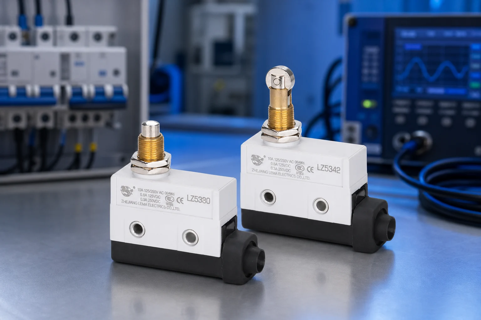
LEMA provides public micro- and limit-switch routes for component inquiry. The LZ15 series micro switch is a public starting point when the mechanical concept calls for a micro-switch review. Confirm the specific series only after LEMA receives the movement, circuit, and validation inputs.
Product recommendation: send the complete door mechanism and control package to LEMA. Do not choose a component when the application requires a complete certified locking assembly or when no model-specific fit evidence exists.
Browse the Micro Switch product line or send an elevator-door RFQ.
FAQs
What does an elevator door micro switch do?
It reports door open or closed state to the control system so the car logic can enable or inhibit related motion sequences.
Is a micro switch the same as an elevator door lock?
No. A micro switch provides electrical feedback; a door lock is a separate interlocking device with its own mechanical and safety requirements.
How much actuator travel is required?
Define free, operate, release, and overtravel from the door hardware drawing so every tolerance stack still reaches a stable contact state.
What causes repeated door-open faults?
Common causes are insufficient travel, loose mounting, contamination on the actuator, or wiring that does not match the required contact logic.
Can any micro switch be used in an elevator interlock?
No. Use only devices approved for the documented elevator control architecture and confirm ratings, mounting, and validation against that design.
What should an OEM include in the RFQ?
Provide door travel, required contact state, mounting envelope, circuit interface, environment, applicable standards references, volume, and sample timing.