
Normally closed and normally open describe the circuit before the actuator moves, and that free state is a design decision. Choose it from what the system must do when a wire breaks or a bracket loosens, not from which terminal is easier to reach.
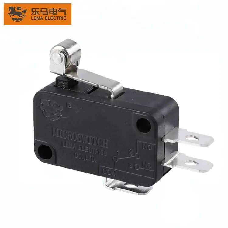
Part 1. What do normally closed and normally open mean?
On a changeover microswitch, COM connects to the NC terminal in the free position and transfers to NO at the operating point. The words describe the resting circuit, nothing more.
| State | Free position | Operated position |
|---|---|---|
| Normally open path | Circuit open | Circuit closed |
| Normally closed path | Circuit closed | Circuit open |
| Changeover use | Both paths available | States swap together |
Series documentation in the LEMA Micro Switch product line states which arrangements each family offers, so confirm availability before the schematic freezes.
Part 2. How does failure behavior drive the state choice?
Ask what the controller should believe when the signal disappears. A broken conductor, an unplugged connector, and a failed contact all read the same as an open circuit.
Wiring the function so that open means stop turns most of those faults into safe stops instead of silent failures. Interlock examples in the elevator door interlock guide apply exactly this reasoning to door travel.
Part 3. When is normally open the right default?
Normally open suits event detection without a hazard behind it: counting products on a line, confirming a tray is seated, or lighting an indicator. The circuit stays quiet until something happens, which keeps standby current at zero and logic simple.
Presence-style detection also tolerates NO wiring when a separate mechanism supervises safety, leaving the microswitch a pure information role.
Part 4. When does normally closed earn its place?

Normally closed carries the supervision cases. Guard doors, overtravel stops, and permissive chains want a circuit that is intact while conditions are correct, so any interruption removes the permission.
| Scenario | Preferred path | Reason |
|---|---|---|
| Guard or cover supervision | Closed when safe | Loss of signal removes the run permission |
| Product counting | Open until the event | No hazard behind a missed count |
| End-of-travel stop | Closed until the limit | Wire break reads as the limit reached |
Terminal identification for either choice follows the continuity method in the terminal wiring review.
Part 5. How should the controller read each state?
Controller configuration completes the decision. The input’s idle level, debounce time, and alarm logic must match the chosen free state, or the schematic and the firmware will disagree in the field.
- Write a state table covering free, operated, and fault conditions.
- Keep signal current inside the model’s minimum applicable load.
- Debounce in firmware against snap-action bounce windows.
- Alarm on impossible state combinations where two switches supervise one motion.
Part 6. What belongs in the RFQ and Fit Boundary?
RFQ input checklist
- Schematic with the required free and operated states
- Failure expectation for each supervised motion
- Load, voltage, and controller input specification
- Actuator travel, mounting, and environment notes
- Volume and sample timing
Fit Boundary
This guide decides a contact state for control logic. It does not certify a safety category, provide monitored redundancy, or replace the model document’s contact ratings.
Part 7. How can LEMA support a contact state inquiry?
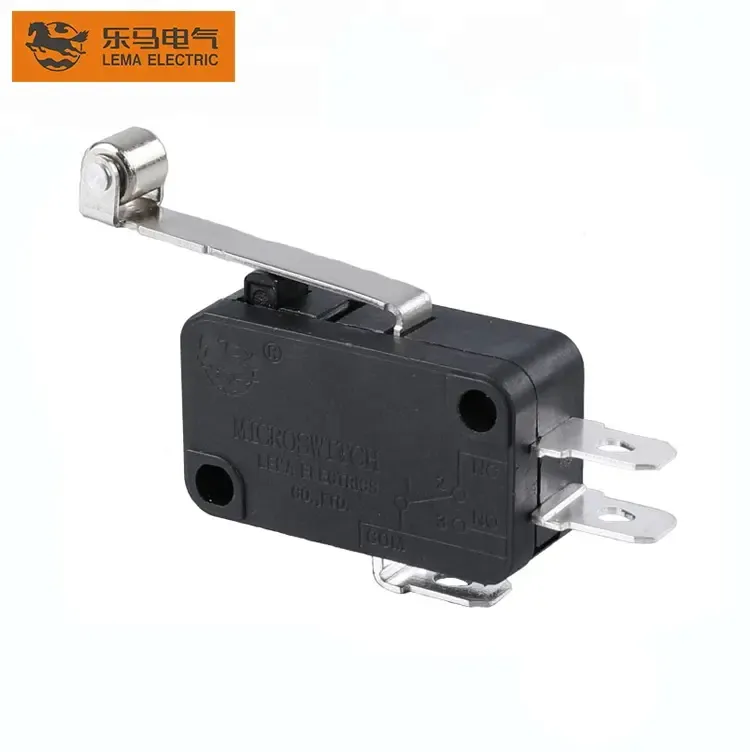
Changeover families keep both options open until validation. The KW7 series micro switch page is a public LEMA route for reviewing contact arrangements against a state table.
Product recommendation: submit the state table with the schematic so the review covers logic and load together. Choosing terminals on the bench without that table is how inverted logic ships.
Send an OEM switch RFQ with the state table attached.
FAQs
What is the difference between NC and NO on a microswitch?
NC conducts in the free position and opens when actuated; NO does the opposite. Both usually exist on one changeover contact.
Why do safety interlocks prefer normally closed wiring?
A broken wire or failed contact reads as an open circuit, so a closed-when-safe design turns those faults into stops rather than silent failures.
Can one microswitch provide both NC and NO?
A changeover type exposes COM, NC, and NO terminals, letting the designer wire either path or both.
Does the free state change the switch’s rating?
No, but each path must still be checked against the model’s documented load limits, including minimum applicable load for signal circuits.
How should the controller handle contact bounce?
Apply input debounce matched to the snap-action bounce window and validate timing on production assemblies.
What should a contact state RFQ include?
Include the schematic, state table, failure expectations, loads, actuator travel, environment, volume, and sample timing.