
To test a foot switch, identify its intended contact function, safely isolate and disconnect it from the equipment, and check the specified contact pair in both released and operated states. A multimeter can help screen an ordinary mechanical switch for an open circuit or an inconsistent connection. It cannot establish a pedal’s load rating, safety approval or suitability for a particular machine. This guide covers a repeatable inspection record for industrial foot controls, including the pedal, cable and connector, so you can distinguish a switch fault from a harness or controller problem.
Do not apply this procedure unchanged to electronic, variable-speed, medical or safety-rated pedals. Their circuits and verification requirements may be different. Follow the exact equipment and pedal documentation.
Identify the device before choosing a test
A foot-operated device may be a simple contact switch, a potentiometer, an electronic sensor or a multi-stage control. Some pedal assemblies have several independent contacts. Others send a coded signal to a controller. Testing every pair of wires as though it were a dry contact can produce misleading results or damage an electronic assembly.
Read the order code and terminal diagram. Record whether the action is momentary or maintained, whether the intended contact is normally open or normally closed, and whether the connector contains additional circuits. Do not infer function from a connector’s shape, wire colors or the appearance of a similar pedal. The relevant drawing should describe the particular order code being tested.
Das industrial electric foot switch selection guide explains the wider specification questions. This test guide focuses on locating an existing fault without changing those requirements.
Prepare an isolated, controlled test
Follow the site’s energy-control procedure and verify the safe condition before touching the switch wiring. Address movement, pressure and other stored energy as well as electrical supplies. OSHA’s hazardous-energy overview provides the servicing context. A foot pedal or stop button by itself is not an energy-isolating device.
Use a meter suitable for the work and follow its instructions. Resistance and continuity checks require a de-energized circuit. Disconnect the switch sufficiently to avoid measuring a parallel path through a relay, controller or another contact. A reading taken through the whole machine does not necessarily describe the pedal.
Before disconnecting anything, photograph the original connection, identify the connector orientation and label conductors against the drawing. Keep the isolated pedal on a stable, dry bench. Do not perform a test while the connected machine could start or move. Work on unfamiliar, damaged or safety-related equipment should go to the responsible qualified technician.
Inspect the pedal, housing and cable first
Check for cracks, a distorted base, a loose cover, damaged tread and debris that obstructs normal movement. Inspect the visible cable jacket along its accessible length. Look closely at transitions near the pedal and connector, where repeated bending or tension may concentrate. A pinched cable or pulled connector can mimic a contact failure.
Operate the isolated pedal through its intended travel. Observe whether it returns or remains operated according to its specified action. Listen for unusual scraping, but do not treat an audible click as electrical proof. Check whether the mounting position or surrounding objects could prevent full travel in the actual installation.
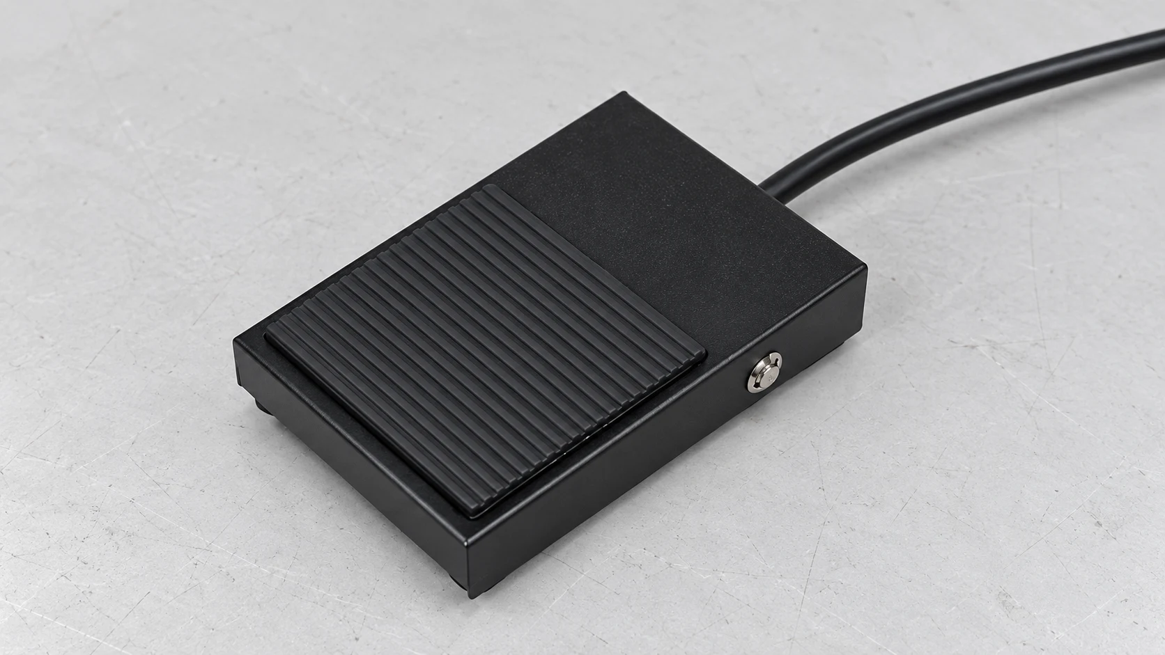
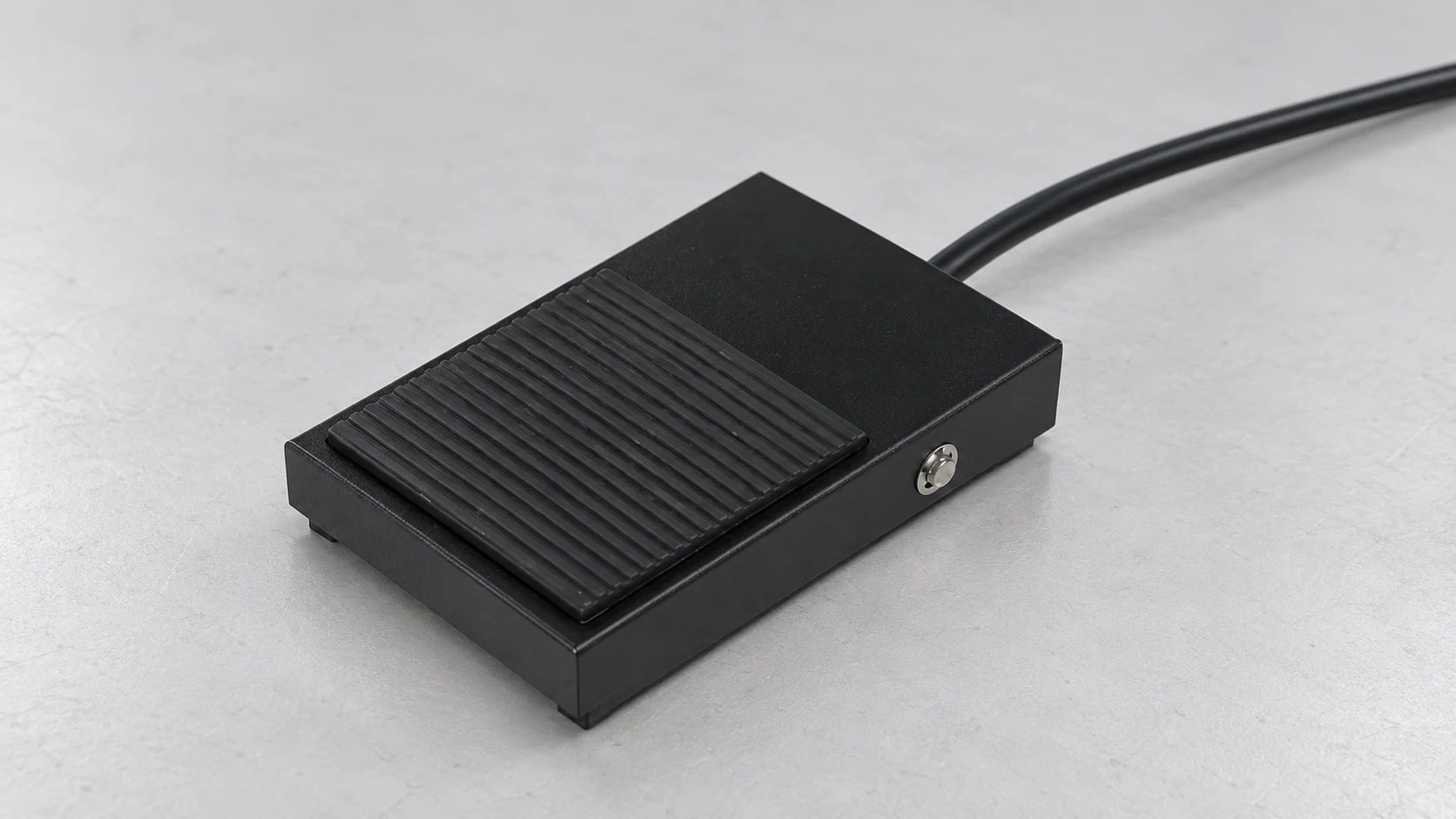
The pictured example comes from the LEMA LF product family. It is a reference for external form only. The exact contact function, cable configuration and ratings must come from the selected model documentation.
Check released and operated contact states
First confirm that the meter and leads work as described in the instrument manual. Identify the contact pair on the pedal drawing and place the probes on the corresponding isolated terminals or approved connector test points. Avoid spreading connector sockets or damaging their protective finish with oversized probes.
Record the released reading. Operate the pedal normally and record the second reading. Release it and confirm the expected return state. Repeat this sequence while keeping the probe connections steady. For a maintained pedal, use its specified operating sequence to change and release the state; do not assume it behaves like a momentary device.
A normally open pair should change from its specified open state to a conductive state when operated. A normally closed pair should show the opposite behavior. A changeover assembly requires checks of the individual contact pairs, using the common terminal identified by the drawing. Do not assume every pedal has three terminals or a universal pin assignment.
For background on operation modes, see maintained versus momentary foot switches. Use the documented electrical criteria for the particular assembly; this article does not supply a universal resistance threshold.
Record observations without overstating the result
| Observation on an isolated mechanical contact | Mögliche Erklärung | Useful follow-up | What the check does not establish |
|---|---|---|---|
| Expected open and conductive states repeat consistently | The basic contact action is present at the test points | Check the harness, controller and installation requirements | Load capability, endurance or complete machine safety |
| No state change | Wrong terminals, incomplete actuation or damaged contact | Confirm drawing and travel before concluding the contact has failed | Which internal part is damaged |
| State changes when the cable is gently moved | Intermittent conductor, connector or test connection | Stabilize probes and identify the affected cable section | A repair method approved for the assembly |
| One circuit passes but another does not | Independent circuit fault or incorrect contact identification | Record each pair separately against the actual diagram | Correct operation of the entire multi-contact pedal |
| Conductive reading persists after release | Maintained action, mechanical obstruction or contact damage | Confirm the specified action and inspect mechanical return | That the equipment is safe to operate |
The table is a qualitative interpretation aid. An acceptable value, test current or measurement method must come from the applicable device specification and test procedure.
Understand the limits of a continuity sound
A continuity buzzer indicates that the meter sees a path within its own detection criteria. Different instruments can sound at different conditions. It is useful for finding gross open circuits, but a beep alone is not a contact-resistance acceptance test. Probe resistance and unstable connections can also affect an ordinary two-lead reading.
Do not use a handheld meter result to approve a pedal for switching a motor or an inductive load. Electrical duty depends on more than the presence of continuity. The foot switch contact rating guide discusses why the actual load and operating duty matter.
If the application requires a controlled low-resistance, insulation or endurance test, use the specified equipment and procedure. Record the instrument and test conditions. Do not improvise a high-voltage test or energize a disconnected unknown pedal merely to see what happens.
Check the cable and connector as a separate path
If permitted by the assembly documentation, check the isolated harness conductors between their identified endpoints. Keep the results separate from contact tests. A combined pedal-and-cable measurement can reveal an intermittent path but may not locate whether the defect lies in the pedal, strain relief, cable or connector.
Inspect mating connectors for bent contacts, contamination and incomplete engagement. Confirm that connector pin identification follows the drawing’s viewing direction. A pin diagram viewed from the opposite side can reverse the apparent arrangement. See the foot switch connector guide for the compatibility questions to preserve during repair.
Use gentle movement only within normal cable handling, with the circuit isolated and supported. Do not pull on the cable, sharply bend it or repeatedly flex a visibly damaged section. Record intermittent behavior and remove damaged assemblies from service pending an approved repair or replacement decision.
Continue to the receiving input when the pedal passes
A consistent isolated contact check moves the investigation downstream; it does not end it. Confirm the harness connection and input assignment against the machine drawing. A controller may require a particular input reference, a programmed operating mode or a permissive condition before it responds.
The following RealPars lesson uses a push button to explain digital input troubleshooting. The same separation between a mechanical field contact, its wiring and the receiving input helps frame an ordinary foot-control investigation. The example does not establish the pinout of a LEMA pedal and should not be copied as a universal live-test procedure.

RealPars digital input teaching source · Watch on YouTube.
Close the test with a repair and validation record
Record the pedal identification, symptom, contact pairs, released and operated readings, cable observations and decision. Preserve the original drawings and connection photographs with the service record. Avoid the vague statement “pedal tested good” when only one contact pair or one operating state was checked.
Use an approved replacement that matches the function, mounting, connector, contact arrangement and application duty. After reassembly, complete the authorized return-to-service process and validate the affected control functions. Keep temporary test leads and simulations out of the final installation. For an OEM inquiry, send LEMA the exact circuit requirements and test observations rather than asking for a replacement solely by appearance.
Häufig gestellte Fragen
Can I test a foot switch while it is connected to the machine?
An in-circuit reading can include parallel paths and may be unsafe. Follow the equipment procedure; isolated continuity checks are for de-energized mechanical contacts.
What resistance proves that a pedal is good?
There is no universal acceptance value. Use the exact model’s specification and the required measurement method.
Why does the pedal work on the bench but fail when installed?
Mounting stress, limited travel, cable damage, connector problems or controller conditions can cause installation-dependent faults.
Does a multimeter test confirm a safety foot switch?
No. A basic contact check does not validate a safety function, required diagnostics or the complete machine control system.