
Micro switch terminal mechanical strength is not the same as connector mating force or cable retention. A receptacle can hold a wire securely while its installation bends the switch blade or loads the housing. Define which interface is being assessed, the direction of force and whether the test is destructive before setting an acceptance procedure.
Das Mikroschalter der Serie KW7 is the LEMA product reference illustrated here. Its photograph identifies the external product, not an unlisted rating, accessory compatibility or test result. Obtain the current specification for the full order code before approving an assembly.
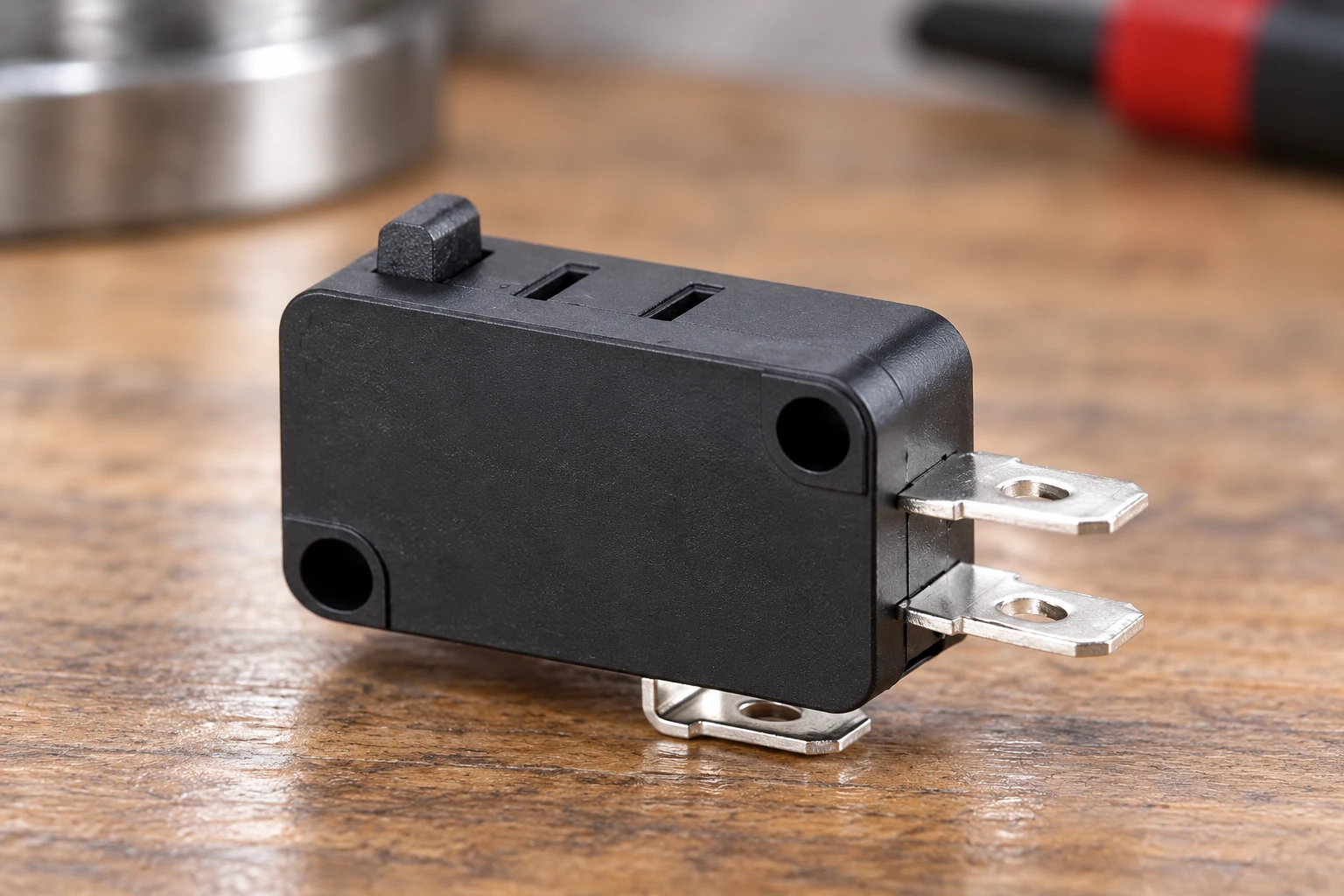
Separate Mating Force, Retention, and Terminal-to-Housing Strength
Mating force is the force needed to engage a receptacle or connector with the switch terminal. It reflects contact geometry, spring action, alignment, friction, and any locking feature. It matters during assembly because the mating load must pass through the terminal and its supporting structure. A connection that feels secure after assembly may still impose an unsuitable insertion load, especially when the operator pushes at an angle or cannot support the switch body.
Retention describes resistance to separation after mating. For a push-on receptacle, this may come from spring contact pressure, a positive latch, or both. Retention must be evaluated using the specified mating component and an appropriate disengagement method. Pulling an unlocked connector, pulling against an engaged latch, and operating a release feature measure different behaviors. None should be substituted for another without an explicit engineering rationale.
Terminal-to-housing strength concerns the attachment of the terminal within the switch itself. Loads may be resisted by formed features, molded material, internal supports, or other construction details. This interface can be damaged even when the mating connector remains intact. Terminal movement, housing cracking, or disturbed internal geometry can compromise switching performance without causing immediate separation. A connector retention result therefore cannot establish terminal-to-housing strength.
| Eigentum | Primary load path | Relevant concern | Nützliche Beweise |
|---|---|---|---|
| Mating force | Connector into terminal and switch support | Assembly damage or incomplete engagement | Controlled mating observation and functional checks |
| Connection retention | Harness or connector away from terminal | Unintended disengagement | Defined withdrawal method and separation behavior |
| Terminal-to-housing strength | Terminal into its internal anchorage | Terminal movement or housing damage | Targeted loading and post-test inspection |
| Sideways load resistance | Harness through an offset terminal connection | Bending, twisting, or progressive loosening | Installed-geometry assessment and electrical verification |
| Harness support effectiveness | Wire bundle into clamps and surrounding structure | Service loads reaching the switch | Routing review and representative assembly evaluation |
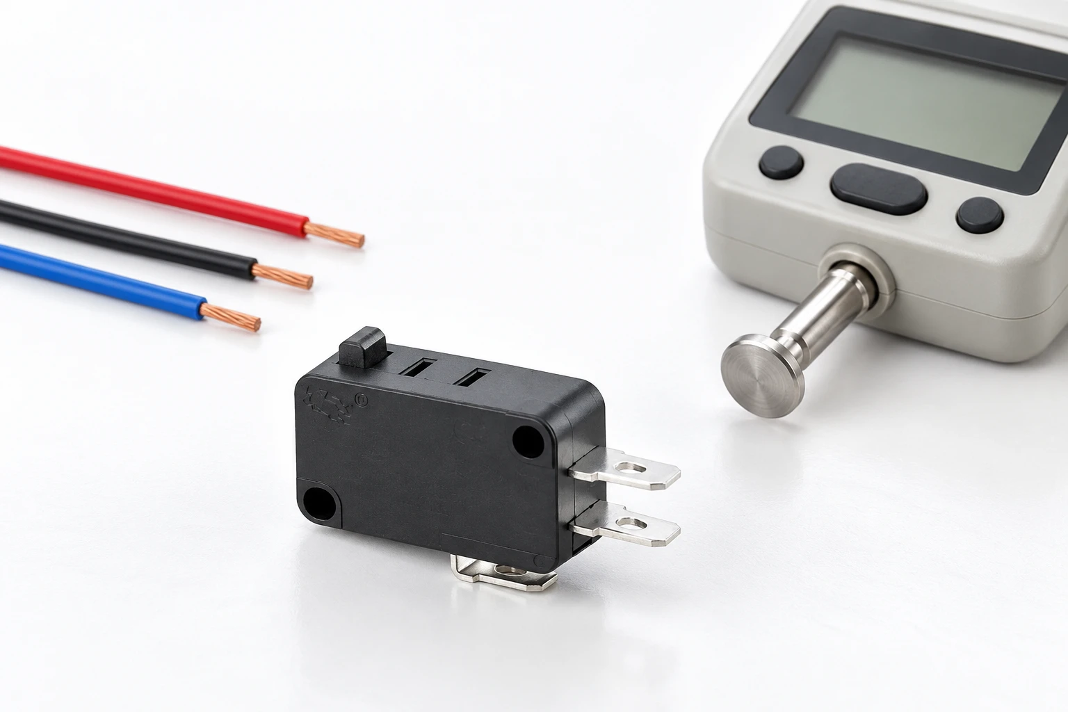
Define the Load Path Before Choosing a Test
Begin with the installed assembly and trace where force enters, where it reacts, and which interfaces carry it. During mating, the reaction may travel through the switch housing into its mounting bracket. During servicing, a technician pulling the wire instead of the connector may load the conductor crimp, receptacle, switch terminal, and housing anchorage in sequence. During operation, an unsupported harness may apply an alternating bending moment rather than a straight pull.
Describe these conditions in the verification plan before selecting test equipment. Identify the intended mating direction, accessible service motions, mounting compliance, connector orientation, and nearby restraints. Include relevant tolerances and build variations. The purpose is not to reproduce every possible misuse, but to distinguish expected loads from separately assessed abnormal conditions. This prevents an easy laboratory test from becoming the default acceptance criterion for an unrelated installation risk.
Support the Assembly Without Concealing Weakness
A fixture should reproduce the support that the production installation actually provides. If the switch is mounted through its designated mounting features, the test should normally react load through those features. Clamping the housing directly beside the terminal can suppress deformation that would occur in the product. Conversely, leaving a normally supported switch hanging from its terminals can create a failure mode that the installed design does not experience.
Support requirements also apply during production assembly. Operators should not use a fragile terminal as a handle or force a connector into alignment by bending the terminal. Where insertion loads require backing support, provide access and tooling that support the intended structure without contacting the actuator or damaging insulation. Document the assembly motion so that acceptable parts do not depend on an experienced operator informally compensating for poor access.
Treat Sideways Load as a Distinct Mechanical Risk
A sideways harness load creates bending at the terminal and may twist its anchorage. Its effect depends on where the load is applied and how far that point lies from the supported terminal region. A straight withdrawal test does not capture this geometry. Even a modest sideways load can become important when a stiff connector or tightly bundled harness acts as a lever against an unsupported terminal.
Evaluate lateral loading in directions relevant to the installation rather than assuming the terminal behaves equally in every direction. Consider whether neighboring wires, enclosure walls, or assembly tools can push the connector off axis. Inspect for permanent terminal displacement, changes in connector seating, housing distress, and altered electrical behavior. When flexing is part of normal use, assess the repeated motion and its load path instead of relying only on a static bend assessment.
Distinguish Destructive Qualification from Routine Checks
Destructive testing explores strength, failure mode, or margin by loading a sample until a defined endpoint or failure occurs. It can reveal whether the weakest element is the wire termination, receptacle grip, terminal metal, or switch anchorage. The result is meaningful only with the loading direction, fixture, loading method, sample condition, and failure definition recorded. A peak reading alone cannot explain whether the observed failure represents the intended requirement.
Routine checks serve a different purpose. They confirm assembly features or process consistency without intentionally consuming the product’s mechanical life. Appropriate checks may include connector seating inspection, latch confirmation, routing verification, and an approved electrical test. A manual tug should not be introduced casually: an uncontrolled pull may damage a sound connection, miss an incomplete engagement, or create inconsistent operator judgments. Any proof check needs a defined method and demonstrated nondestructive suitability.
Keep qualification samples distinct from deliverable assemblies unless reuse is explicitly justified. A sample that survives an overload can contain hidden damage or a shifted contact interface. Passing an electrical check immediately afterward does not automatically restore its production status. Similarly, a destructive result should not be converted into a shop-floor proof load by applying an arbitrary allowance. The relationship requires an engineering basis tied to the actual failure mechanisms.
Design Fixtures That Produce Interpretable Results
Fixture alignment should match the intended test direction and avoid introducing unintended torque. Grip the connector or conductor at the location relevant to the requirement. If the purpose is connector withdrawal, a grip that crushes the receptacle can change its retention. If the purpose is wire termination integrity, gripping the connector body instead of the wire bypasses the interface under examination. State precisely what is restrained and what is loaded.
Provide enough visibility to observe movement and identify the first meaningful damage event. Record the specimen condition before loading, including terminal orientation, connector engagement, wire routing, and switch mounting. Where fixture compliance or slippage could influence the result, assess and control it. Test equipment suitability should cover the expected loading behavior, not merely the ability to display a force reading.
For terminal-to-housing evaluation, distinguish anchorage failure from terminal bending caused by the loading attachment. The attachment must transmit the intended load without creating an artificial stress concentration or reinforcing the terminal. When complete separation is not the relevant endpoint, define how displacement, visible damage, or loss of function will be detected. Photographs and observations can be as important as the recorded load in explaining the outcome.
Build Acceptance Criteria Around Evidence
Set acceptance criteria before testing, using applicable switch documentation, connector requirements, product safety obligations, and installation-specific risk analysis. Do not borrow a force requirement from a superficially similar terminal. Differences in terminal geometry, housing construction, contact arrangement, or mounting can make that comparison misleading. Where supplier information is incomplete, resolve the intended application and verification approach rather than treating missing data as permission to assume equivalence.
Define the test boundary and sample disposition
A mechanical assessment must say where force enters, which part is supported, the direction and rate of loading, and the failure or displacement criterion. Terminal-to-housing strength is a different boundary from wire-to-receptacle retention. Photograph the fixture and retain the sample identity. A test performed with a free cable loop can impose a different bending moment from a test aligned with a terminal axis.
Do not return destructively tested or potentially damaged samples to production stock. Where the purpose is a routine assembly check, define a supported nondestructive method instead of borrowing a qualification load. After a justified mechanical exposure, complete the specified functional and visual checks, preserving any change in terminal position. Ask for the exact termination drawing and relevant assembly limits; photographs alone cannot provide a pull-force specification.
Technical references and the scope of this review
IEC 60068-2-21 robustness of terminations: The IEC method addresses terminations and mounting devices subjected to assembly or handling stress. Select the applicable method and acceptance requirement; no universal pull force follows from a family photograph.
HSE controlled electrical testing: Mechanical handling can affect later electrical assessment. Keep the sample isolated and use the appropriate procedure when checking function after a mechanical test.
For the wider component decision, see Auswahl eines industriellen Mikroschalters für OEM-Schalttafeln. Complementary checks are covered in Micro Switch Terminal Types: Solder, PCB and Quick Connect und Micro Switch Failure Modes: Evidence and Root-Cause Checks. These pages address separate questions and do not replace the acceptance evidence defined here.
Further learning
This independent lesson explains stress and strain, providing physical background for mechanical loading. It does not assign a test force or fastening setting to the illustrated switch.
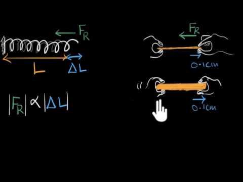
Watch Stress & strain | Class 11 (India) | Physics | Khan Academy — Khan Academy India – English
Häufig gestellte Fragen
Is connector retention the same as terminal strength?
No. They assess different interfaces and can involve different failure mechanisms.
Can I use a universal pull force?
No. Use the applicable method and limits for the exact terminal and assembly.
Can a destructively tested sample return to stock?
Keep it segregated under the test and disposition procedure; do not treat it as ordinary unused material.
What information belongs in a mechanical test record?
Identify the sample, support, loading point, direction, method, acceptance criterion and observed result.