
Micro switch solder joint thermal fatigue is an assembly reliability question: repeated temperature changes can load a soldered connection when joined parts expand differently. A switch’s mechanical operating life does not establish the life of its installed solder joints. To evaluate the risk, identify the actual terminal and joint construction, describe the equipment’s thermal history, and agree a test and inspection plan for the finished assembly. This guide helps OEM teams request useful evidence for a KW7 installation. It does not predict a failure cycle count, prescribe a thermal profile or claim that NASA research qualifies a Lemaele product.
Keep terminal solderability, process damage and fatigue separate
Solderability concerns whether the terminal surface can form a suitable joint under the approved process. Process damage concerns what happened while the joint was made, including inappropriate heating or mechanical loading. Thermal fatigue concerns accumulated damage associated with repeated temperature changes after assembly. These questions can interact, but they are not interchangeable. A successful wetting test does not demonstrate years of field service, and a field crack does not by itself identify the original manufacturing cause.
Benutzen Sie terminal solderability after storage guide for incoming surface evidence. Use the micro switch soldering precautions guide for process review. Here the separate focus is the connection after installation and repeated thermal exposure. Maintaining that distinction prevents a purchasing team from accepting a process certificate as proof of a service life requirement it never tested.
What the available research supports
Sandia’s solder joint reliability publication identifies thermal mechanical fatigue as a mechanism associated with temperature cycling and differences in thermal expansion within the joint system. This supports examining the joined materials and their constraints together. It does not supply a KW7 allowable temperature swing or a universal number of safe cycles.
A 1991 NASA record on spacecraft solder fatigue emphasizes defining the thermal environment and validating the completed design. The public record is an abstract, not a downloadable full test procedure. Its spacecraft context is background only. Do not transfer a space electronics qualification profile, lifetime calculation or acceptance rule to an industrial switch assembly without a technically justified application-specific assessment.
For purchasing purposes, the useful lesson is to ask what was joined, how it was restrained and what temperature history it experienced. Material names alone are not a complete model. Two assemblies using the same switch can have different wire support, joint shape and nearby heat sources. A report on one assembly should therefore identify the configuration before its result is used to release another.
Identify the actual KW7 termination
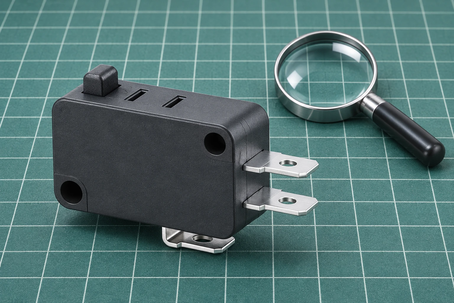
Das Lemaele KW7 series page provides the product family reference and describes terminal and lever variations. Confirm the ordered terminal version before deciding that the connection should be soldered. A photograph of a tab terminal does not establish an approved soldering method, wire size or joint geometry. Obtain the supply drawing and assembly instructions for the selected code, including any restrictions on terminal loading.
Document the conductor, insulation, terminal finish where specified, solder alloy, flux, joint geometry and mechanical support. Record only verified information. Do not fill a missing terminal finish with a common industry assumption. If an assembly uses a removable connector instead of a soldered joint, evaluate that actual interface rather than attaching a solder fatigue requirement to a connection that is not present.
Describe the thermal history the joint will see
List the equipment states that can change local temperature: cold storage, startup, steady operation, shutdown and cleaning or maintenance conditions where relevant. Distinguish the room temperature from the temperature near the terminal and surrounding structure. A nearby heater or a loaded circuit may create a local condition different from the air elsewhere in the enclosure. Where the difference matters, have the responsible team plan suitable measurements.
A test request should describe the intended range, transitions, dwell conditions and expected repetition based on the equipment assessment. These are inputs to agree, not default numbers to copy from a web article. Note whether the test assembly is powered and how its actual configuration is represented. Thermal cycling, electrical load testing and mechanical actuation can answer different questions. State what the proposed test includes and excludes.
| Evidence item | Record to request | Question it resolves |
|---|---|---|
| Montageidentifikation | Switch code, terminal version and drawing revision | Does the result apply to the purchased design? |
| Joint process | Approved materials and controlled assembly instructions | Was the test specimen built like production? |
| Mechanical restraint | Wire routing, support and terminal loading arrangement | What constrains movement around the joint? |
| Thermal exposure | Profile, measurement locations and equipment states | What temperature history was actually evaluated? |
| Monitoring | Electrical checks and inspection timing | Which changes could the evaluation detect? |
| Acceptance basis | Agreed criteria, results and deviations | What conclusion can be released? |
This is a proposed evidence checklist, not a standard or a set of qualification limits. The engineering team should select methods suitable for the product and intended use. A report stating only that a sample passed a thermal test leaves major questions unanswered. Request enough detail to connect the result to the actual joint, profile and inspection criteria.
Review mechanical support alongside the temperature profile
Follow the approved assembly drawing for wire routing and support. Identify whether the harness can transmit movement or tension into the terminal during installation, cover closure or maintenance. A joint may experience more than one type of loading, so avoid treating every crack as a purely thermal event. Document the installed condition before deciding which failure mechanism to investigate.
Do not add a rigid adhesive, extra clamp or encapsulant as an unreviewed improvement. Such changes alter the joint system and may affect rework, inspection and movement. Request a design review of the proposed support rather than assuming that greater restraint always improves reliability. If an approved change is made, record its revision and decide whether earlier test evidence still applies.
Plan inspection to answer a defined question
Keep initial assembly inspection results so later observations have a baseline. Identify samples individually and retain the build records. If electrical continuity or resistance is monitored, define the circuit state, instrumentation and decision rule. A switch contact changing state during actuation is different from an intermittent external connection. The measurement arrangement must allow the investigator to distinguish those possibilities.
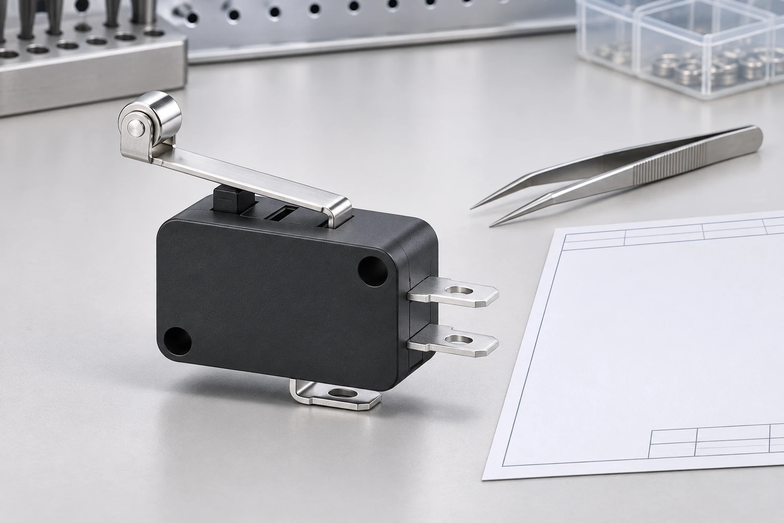
Visual inspection can record a visible crack, disturbed joint or displaced wire, but it cannot reveal every hidden feature. Where further examination is necessary, have qualified personnel choose an appropriate method. Do not claim that an external photograph proves internal integrity. Equally, do not identify thermal fatigue from a photograph alone when manufacturing damage, mechanical stress or other causes remain possible.
Preserve the sample and event history before rework. Reheating a suspect joint can change the evidence needed to understand why it failed. Record the equipment state, symptoms, location and preceding temperature or maintenance events. A useful failure report separates observations from hypotheses and gives the investigator the original configuration. That makes the result more useful than a statement that the switch was bad.
Avoid converting component life into joint life
The KW7 product page lists component operating characteristics, but those values do not establish the fatigue life of every soldered installation. Mechanical operations, electrical switching duty and thermal cycles are different exposures. Do not multiply a daily operating count by the switch’s published mechanical life and call the result a solder joint lifetime. Any life claim needs a defined assembly, environment and validated assessment.
Das micro switch replacement guide provides the broader form, fit and function review when a component must change. Replacing the switch without correcting an assembly problem may leave the same underlying risk. Review the joint process and support together with component selection, and keep the release decision tied to the evidence for the final configuration.
Build a useful supplier enquiry
Send the ordering code, joint drawing, intended thermal environment and relevant load information. Ask which terminal options are approved for the planned connection and what process instructions apply. Request any assembly-specific test evidence, including its sample identity and limitations. Where the requirement is new, agree responsibilities for test design, sample build, acceptance criteria and deviations before ordering a qualification batch.
For future changes, define which substitutions require review: terminal version, conductor, solder materials, support position or nearby enclosure changes. The objective is not to prohibit every adjustment but to prevent an old report being applied silently to a changed joint. Keep the final report, approved drawing and production work instruction linked by revision so the receiving and manufacturing teams can use the same acceptance basis.
Video: temperature and differential expansion
MIT OpenCourseWare’s “What is Temperature?” includes a demonstration using a metal strip to explain temperature and expansion. It supplies background physics for understanding different material responses. It does not demonstrate solder fatigue or qualify a KW7 assembly.
Häufig gestellte Fragen
Does switch mechanical life establish solder joint thermal life?
No. Mechanical operations and thermal cycles are different exposures. Evaluate the installed joint and its actual environment separately.
Can a solderability result replace a thermal fatigue assessment?
No. Solderability addresses forming a joint under a defined process, while fatigue concerns damage associated with repeated exposure after assembly.
Does the NASA record qualify Lemaele KW7 switches?
No. It is historical spacecraft reliability background and contains no qualification result for the Lemaele KW7 series.
Should a suspect joint be reheated before investigation?
Preserve the sample and records first. Rework can alter evidence; follow the responsible technical team’s investigation and repair procedure.