
Micro switch soldering precautions should start with the exact terminal variant and its approved assembly limits. Control the heat delivered to the joint, the time and distance over which that heat reaches the housing, and the mechanical force applied while the terminal is hot. A satisfactory-looking joint does not prove that the switch mechanism or insulation escaped damage. There is no universal iron temperature or contact time that can safely be assigned to every micro switch from its operating-temperature rating.
This guide addresses OEM process preparation and validation for solder terminals. The LEMA KW10-0S solder-terminal product is the illustrated example. Its product identity establishes the termination style, not a qualified soldering profile. Obtain current assembly instructions for the exact order code before releasing a production or repair procedure.
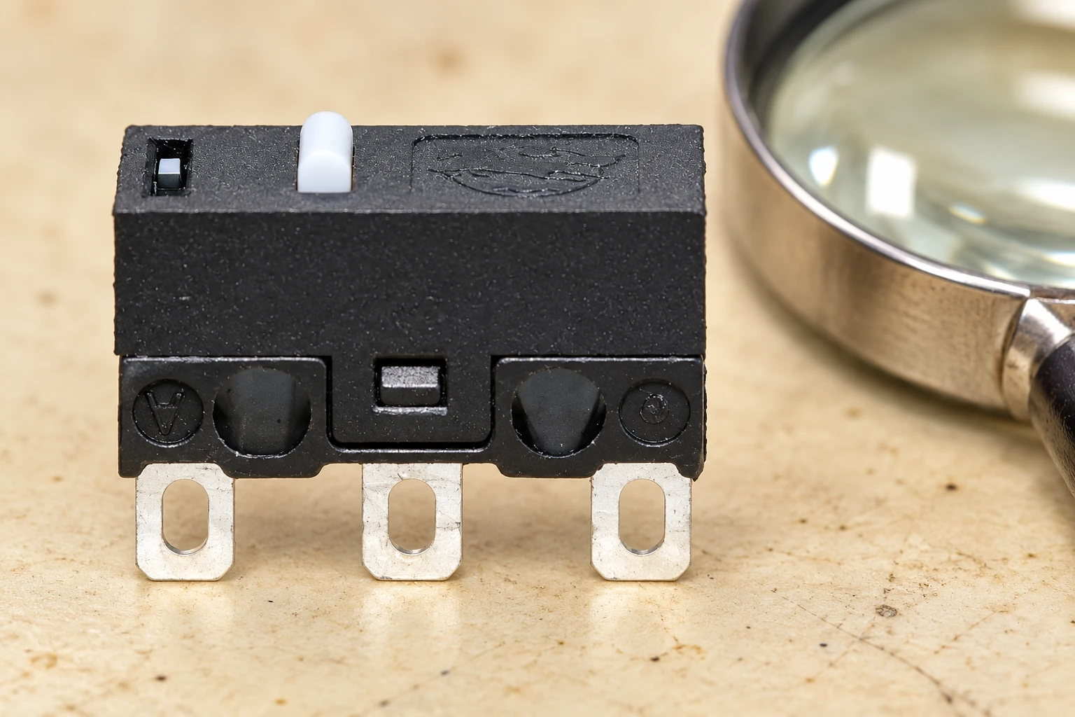
Confirm that the terminal is intended for the process
A switch family may offer solder lugs, PCB pins or other termination arrangements. They can have different mechanical support and assembly requirements even when the housing looks similar. Identify the complete variant and compare the terminal drawing with the intended wire, joint and fixture. A terminal hole does not by itself establish a permissible wire size or a required wrapping method.
For a broader comparison, see the micro switch terminal types guide. The present article focuses on the process after a solder termination has been selected. Do not treat a solder-lug part as reflow compatible merely because it is small, or apply a PCB soldering profile to a loose wired assembly without product documentation.
Ask the supplier which processes have been evaluated and what the limits mean. The description should identify the soldering method, measurement location, permitted exposure, solder and flux conditions, cooling requirements and rework restrictions. If the instruction is abbreviated, resolve the ambiguity before writing a work instruction. An operator should not have to guess whether a temperature refers to an iron setpoint, solder bath or measured component location.
Separate service temperature from assembly heat
The ambient operating-temperature range describes an in-service condition under the component’s specified use. Soldering is a localized thermal process with different heat flow and exposure time. These are different engineering questions. A housing that tolerates a stated ambient temperature is not thereby approved for an arbitrary soldering iron setting or dwell time.
The UK’s National Physical Laboratory code of practice on component and PCB integrity during lead-free processing discusses why processing heat must be considered for component structures and functionality. Its findings provide general process background, not a KW10-specific limit. Use the switch manufacturer’s applicable instructions and validate the actual assembly.
The iron’s displayed setting is also different from the temperature history at the terminal-to-housing interface. Tip condition, contact area, joint mass, wire preparation and fixture contact can change heat transfer. A nominally lower setting combined with prolonged unsuccessful heating may not be a better process. Define a repeatable joint-making method and investigate why a joint is slow to wet rather than simply holding the iron in place longer.
Prepare a controlled process record
| Process item | Evidence or control to define | Reason to hold release |
|---|---|---|
| Component identity | Full switch code, terminal drawing and assembly instruction revision | Only a generic family photograph is available |
| Joint materials | Approved wire, solder alloy, flux and surface preparation | Materials are substituted without a compatibility review |
| Heating method | Equipment, tip, measurement basis and specified exposure limits | Operator judgement replaces an approved process window |
| Mechanical support | Fixture location, wire support and cooling arrangement | Hot terminals are bent or loaded by the harness |
| Inspektion | Joint criteria and post-assembly switch checks | A visual joint check is the only evidence of switch function |
| Rework | Permitted number and type of operations with traceability | Repeated heating is uncontrolled or not documented |
This is a qualitative release checklist. Temperature, time, force and dimensional limits must come from the applicable instructions and validated assembly process; the table deliberately does not invent universal numbers.
Support the wire and protect the terminal
Prepare the wire consistently before bringing it to the switch. Define stripping, conductor condition and any approved pretinning operation in the process. Check that the conductor and insulation can be positioned without excessive force on the terminal. A short unsupported lead can transmit movement to the joint, while an awkward fixture can encourage an operator to use the terminal as a handle.
Use the intended mounting or support features and avoid squeezing the actuator or distorting the housing. Keep the terminal stationary during joint formation and the prescribed cooling stage. Do not bend it to improve wire routing while it is hot. Plan the harness route and mechanical strain relief so that the solder joint does not become the assembly’s only means of retaining the wire.
Review tool access with a representative sample and the production fixture. The operator needs a clear view and controlled access without resting a hot tool against the plastic body or an adjacent terminal. If access is poor, changing the fixture or assembly sequence is generally a more useful engineering action than asking operators to compensate through speed alone.
Control wetting, residues and cleaning
Solderability and heat resistance are related process concerns but are not the same property. Poor wetting can have several causes, including surface condition, materials and process setup. Record the as-received condition and investigate the cause rather than automatically increasing dwell time. NPL’s measurement note on solderability testing and component preheating shows why the thermal history belongs in a defined assessment.
Use an approved flux and cleaning process. Do not assume that a switch can be immersed, ultrasonically cleaned or exposed to a solvent merely because the solder joint can be cleaned that way. Openings around actuators or terminals may create an ingress route, and the compatibility of the housing, markings and internal materials also matters. Seek component-specific cleaning guidance before introducing a process.
Residues and loose solder can create inspection problems around neighboring terminals. Define how residues, bridges, conductor strands and displaced insulation are assessed. Keep process photographs and criteria representative of the actual product. An attractive reference picture is not an acceptance standard unless its relevant features and limits are defined in the controlled inspection instruction.
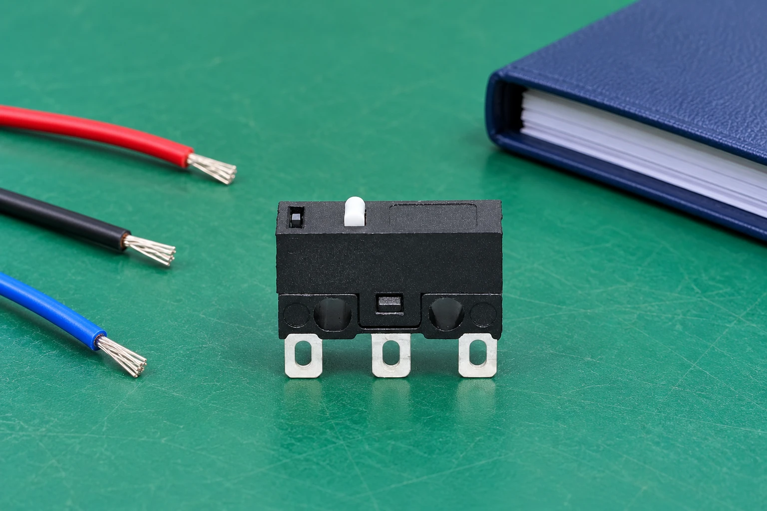
Validate switch function after the joint cools
Choose baseline and post-assembly checks that answer the real risk. They may include actuator return, contact-state operation, terminal position and any specified electrical checks. The procedure should distinguish a damaged joint from a change in switch behavior. A switch that clicks mechanically can still require an electrical examination, and a continuity observation does not establish every insulation or load requirement.
Benutzen Sie isolated micro switch contact-check guide for the separate purpose of identifying contact states. For broader inspection boundaries, the insulation resistance and dielectric strength guide explains why those measurements are different from a basic continuity test. High-voltage or loaded testing needs the appropriate approved procedure and competent personnel.
Validate representative conditions rather than only the easiest joint. Consider the real wire, fixture, operator access and permitted process variation. Record the equipment and component revision so later changes can be assessed. A successful prototype made by an experienced technician does not by itself establish a repeatable production process across other fixtures or operators.
Set a rework boundary before defects occur
Desoldering and resoldering add thermal and mechanical exposure. Define what rework is permitted by the component instructions and the assembly validation, how it is recorded and when a component must be replaced. Do not create a universal permitted rework count from experience with a different switch or connector. The absence of visible melting is not proof that repeated exposure was acceptable.
When a joint fails inspection, identify the defect before choosing the repair. Reheating does not necessarily correct an unsuitable wire size, terminal damage, contamination or poor mechanical support. Preserve evidence when a component fault is suspected, and avoid repeatedly manipulating a terminal to make a marginal assembly pass a temporary continuity check.
For a production change, compare the new process with the accepted baseline. Solder alloy, flux, tip, fixture, wire and component variants can affect the result. Review whether the existing validation still covers the change and record the engineering disposition. Keep commercial availability separate from approval: a substitute on the shelf may require a different assembly assessment.
Include the working environment in process preparation
Soldering also needs a suitable work area and fume controls. The UK Health and Safety Executive’s guidance for solderers addresses health risks associated with soldering fumes. Use the applicable workplace risk assessment, equipment instructions and local controls; choosing a component process window does not replace these arrangements.
A useful inquiry to LEMA includes the exact switch variant, drawing, wire and solder materials, proposed process and the missing limits you need clarified. Request written guidance on assembly and cleaning before production release. Keep the supplier’s response with the process record so purchasing, assembly and quality personnel work from the same component configuration.
Further learning: hand-soldering technique
EEVblog #183 – Soldering Tutorial Part 2 is independent electronics education about hand soldering. It helps explain general joint-making technique, but does not specify a temperature or dwell time for the illustrated LEMA switch. Follow the component’s approved process rather than copying a setting from a general tutorial.
Watch the EEVblog hand-soldering tutorial.
Häufig gestellte Fragen
Can the switch operating-temperature rating set my soldering temperature?
No. Service ambient temperature and localized assembly heat describe different conditions. Obtain the approved soldering limits for the exact component.
Does a shiny solder joint prove the switch is undamaged?
No. Apply the defined joint criteria and the specified post-assembly mechanical and electrical checks after cooling.
Can every miniature switch be reflow soldered?
No. Confirm the terminal variant and the manufacturer’s evaluated assembly process. Small size alone does not establish reflow compatibility.
How many times can I rework a solder terminal?
Use the component instructions and validated assembly procedure to define the boundary. Do not assume a universal rework count.