
Quick-disconnect crimp inspection should evaluate the wire-to-receptacle joint separately from the receptacle’s fit on the switch tab. Confirm the exact wire, terminal, tooling and process, then inspect the conductor crimp, insulation support and completed assembly against the approved criteria. A terminal that slides onto a switch blade does not prove the wire crimp is sound. Equally, a good wire crimp cannot approve a mismatched receptacle or an excessive force applied to the switch terminal.
El LEMA KW7 family provides the visible switch reference in this article. The loose receptacles and wire specimens are explanatory objects, not a claim that a particular crimp terminal, wire size or tool has been approved for every KW7 variant. Use the selected terminal manufacturer’s controlled application specification.
Identify the connection being inspected
A quick-disconnect assembly contains several interfaces: wire strands to the crimp barrel, insulation to its support feature, receptacle to switch blade, and harness support to the surrounding equipment. Define which interface the inspection or test is evaluating.
A loose wire, a loose receptacle and a loose switch blade are not interchangeable findings. Record exactly where movement occurs. The switch-terminal types guide explains the broader terminal options, while the terminal-strength article addresses loads at the switch itself.
Do not use the switch as a convenient anchor for testing a wire crimp. A pull applied through the blade can damage the switch or combine several failure modes into an uninterpretable result. The approved test method should define the specimen boundary and fixture.
Match wire, terminal and tooling before inspection
Record the terminal part number, wire construction, conductor size, insulation dimensions and stripping requirements. Identify the specified crimp tool, die or applicator and the relevant setup. A generic “red terminal” or “small wire” description is insufficient for a controlled production process.
Confirm the receptacle’s mating dimensions and material or finish requirements separately from its wire range. A crimp barrel can suit the wire while the mating section is wrong for the switch tab. Obtain both the switch drawing and the terminal application specification.
Do not infer approval from a successful hand fit. The terminal’s retention, electrical performance and environmental suitability depend on the complete combination and its stated conditions. Supplier documents should resolve those questions before production trials become informal approval.
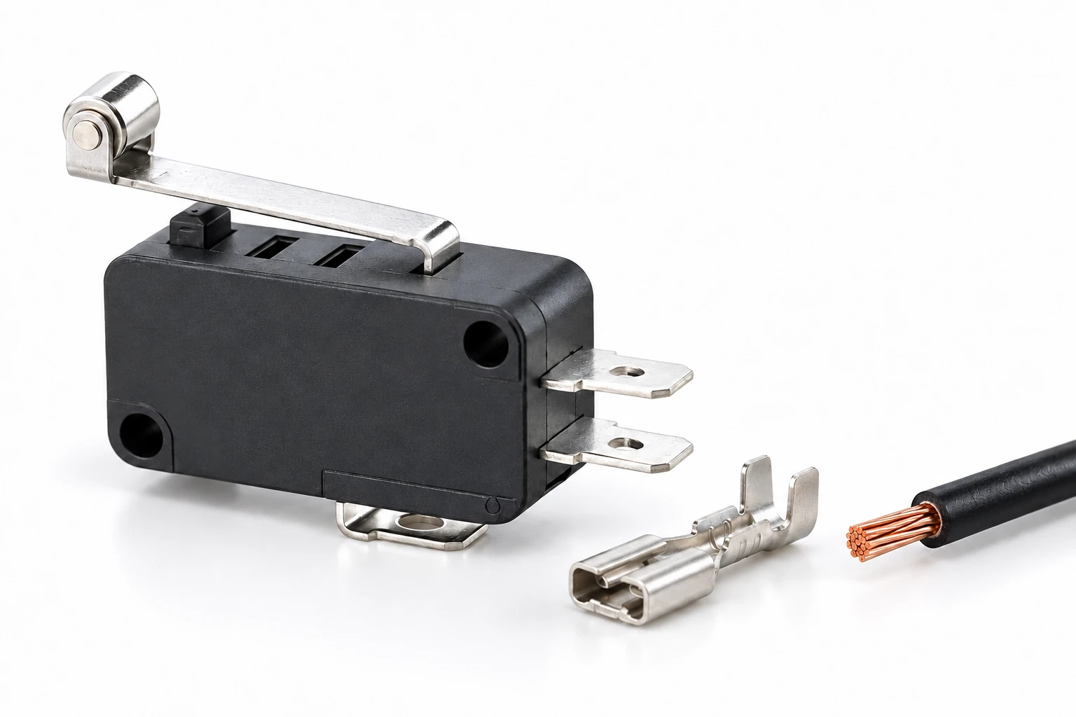
Inspect the prepared wire
Check the stripped conductor against the approved preparation criteria. Look for damaged, missing, folded or displaced strands and insulation that was cut or stretched during preparation. The required strip length must come from the terminal specification, not a photograph of a similar connector.
Inspect the wire before inserting it into the barrel. After crimping, some preparation defects may be difficult to distinguish from forming defects. Keep representative setup samples and record preparation changes when investigating a recurring problem.
Do not twist, tin or otherwise modify the strands unless the approved process calls for it. Added solder or an improvised treatment can change how the joint forms and behaves. If the equipment specification requires a special wire construction or preparation, preserve that requirement in the work instruction.
Inspect the conductor crimp as a formed joint
Check that the conductor is located and captured as required by the terminal design. Look for an incompletely formed barrel, displaced strands, inappropriate protrusion, cracks or obvious distortion. The relevant acceptance features differ between open-barrel and other terminal constructions.
Use the manufacturer’s criteria for crimp height, width or other controlled characteristics where specified. Do not invent a universal crimp dimension or judge every terminal by the same visual rule. A joint that looks compact can still be outside the approved forming window.
El NASA wiring-workmanship standard record is an authoritative reference for the importance of controlled wiring and crimping workmanship. Its scope and acceptance provisions do not automatically become the contract requirements for an ordinary commercial switch assembly; use the standard actually invoked by the equipment specification.
Review insulation support separately
An insulation-support feature helps manage the wire near the conductor joint, but it should not be confused with the electrical crimp itself. Check its position and forming condition against the specific terminal criteria. The wrong insulation diameter can make an otherwise plausible setup unsuitable.
Look for cuts, severe deformation, loose support or a wire held in an unintended position. Do not assume that squeezing the insulation more tightly always improves the assembly. The process must avoid damaging the insulation while providing the intended support.
Beyond the terminal, provide the harness support needed by the equipment. Repeated bending or a heavy unsupported wire can load the joint even when its initial workmanship is acceptable. Record the bend and restraint arrangement in the complete harness review.
Use mechanical tests within their proper scope
A defined pull test can provide useful information, but its method, specimen preparation and acceptance limit must be specified. Identify whether the test is destructive, how the insulation support is treated and where the specimen is gripped. Do not substitute an assembler’s tug for a documented test where a controlled result is required.
A satisfactory pull result alone does not establish every aspect of electrical or environmental performance. Conversely, a continuity reading can miss a mechanically weak joint. Select the combination of inspection, dimensional control and testing required by the approved process.
El HSE electrical-testing guidance provides safety context where an electrical investigation is involved. Crimp setup and destructive mechanical testing should remain separated from an energized machine unless an appropriate controlled procedure explicitly requires otherwise.
| Inspection boundary | Check against | Do not confuse with |
|---|---|---|
| Wire preparation | Approved strip and conductor condition criteria | Appearance after an unknown repair |
| Conductor barrel | Terminal-specific forming and dimensional limits | A generic visual tightness judgment |
| Insulation support | Specified insulation range and forming criteria | Electrical conductor crimp quality |
| Mating section | Switch-tab and receptacle compatibility | Wire-range compatibility alone |
| Mechanical test | Defined fixture method and acceptance limit | Pulling against the mounted switch blade |
Check the receptacle-to-switch interface
After the crimp process is accepted, verify the mating section against the switch tab drawing. Inspect blade condition, alignment, receptacle engagement and support. Apply assembly force in the permitted direction without bending or twisting the switch terminal.
Do not use repeated mating to make an incorrect terminal fit. If engagement or withdrawal is abnormal, preserve the parts and compare the actual dimensions and specifications. A receptacle that is too tight may transmit damaging force, while one that is too loose may not provide the intended contact behavior.
The switch-tab mechanical limits and the crimp-joint test requirements are separate controls. Document both in the assembly specification so a later supplier change to either part receives the appropriate review.
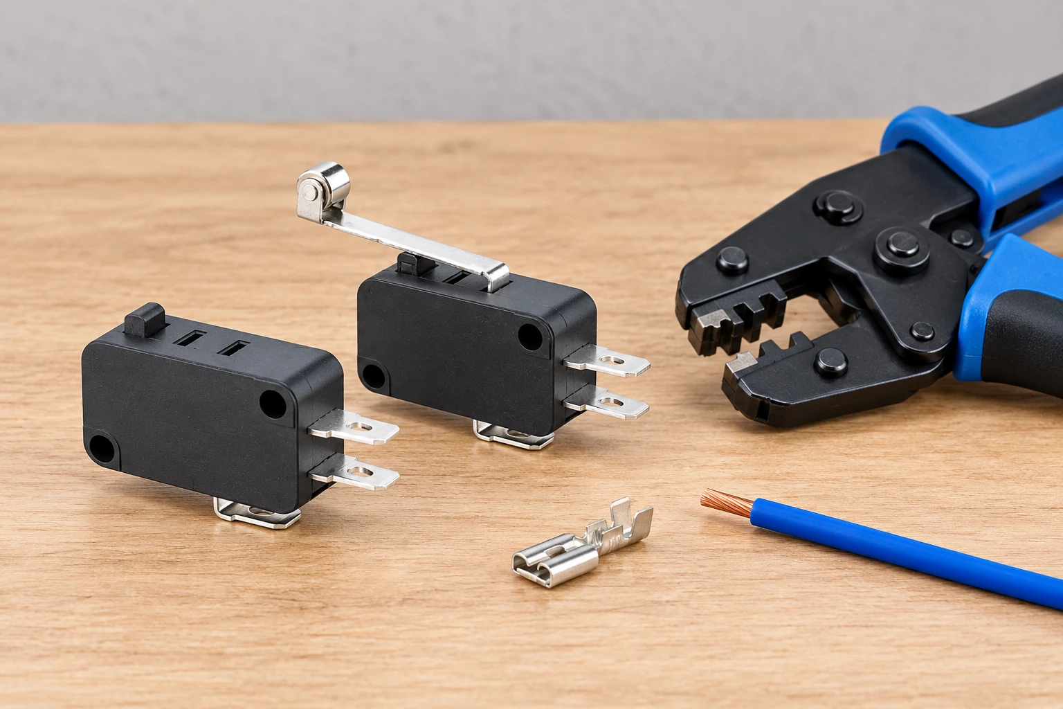
Control setup, sampling and traceability
Keep the tool, terminal and wire identities with the production record. Record setup verification, any required dimensional checks and the applicable sampling plan. Define what happens after a tool adjustment, applicator repair, terminal-lot change or wire substitution.
A small number of acceptable first-off samples does not automatically approve an uncontrolled process for an entire production run. The quality plan should identify ongoing checks and the response to a failed result. Quarantine affected work while the boundary of the problem is established.
For an investigation, retain failed and comparison specimens without re-crimping them first. Record their original process conditions. Reworking a specimen can erase the evidence needed to distinguish preparation, tool setup, terminal mismatch and handling damage.
Provide complete evidence with an OEM inquiry
Send the switch order code and tab drawing together with the receptacle part number, wire specification, tooling, process instructions and observed defect. Include close photographs of the wire joint and mating section separately. State which acceptance document applies and which results have actually been measured.
Utiliza el LEMA inquiry page for the switch-side interface questions and the terminal supplier for its crimp-process requirements. The micro switch failure guide can help keep a connection fault from being incorrectly classified as an internal switch defect.
Further learning: deformation under mechanical load
Khan Academy India – English: Stress & strain | Class 11 (India) | Physics | Khan Academy. Khan Academy explains stress and strain, providing background for deformation under mechanical loading. It is not a crimping tutorial, tool setup instruction or acceptance standard for the pictured terminal.
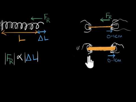
Watch Stress & strain | Class 11 (India) | Physics | Khan Academy.
Preguntas frecuentes
Does fitting the switch blade prove that the crimp is good?
No. The wire-to-barrel joint and the receptacle-to-blade interface are separate boundaries. Confirm the correct wire, terminal and tool process, then verify mating compatibility and assembly loads independently.
Can I use one crimp dimension for every terminal?
No. Acceptance dimensions and visual features belong to the specific terminal and application specification. Open-barrel and other constructions can have different requirements; do not copy values from a similar-looking connector.
Can I test the crimp by pulling against the switch?
Use the defined test specimen and fixture. Pulling through a mounted switch can load its blade or housing and combine several interfaces. It may damage the switch without providing a valid wire-crimp test result.
Is a continuity check enough for crimp acceptance?
It answers only a limited electrical question under the stated conditions. The approved process may also require preparation checks, dimensional control, visual inspection and mechanical testing. Keep each result within its actual scope.