
Limit switch paint overspray protection starts with keeping coating material away from the moving actuator, its operating path, the enclosure entry and the identification needed for maintenance. An ingress rating does not establish resistance to paint deposits, solvents or a spray-booth atmosphere. Prefer process sequencing and a reviewed installation arrangement over improvised bags or tape on a working switch. This guide explains how to plan that review and record a return-to-service check. It does not approve an ordinary LEMA limit switch for an explosive atmosphere, certify a protective cover or prescribe a paint-removal chemical.
Decide whether the switch needs to be present during painting
Start with the production sequence. If the equipment design allows the bracket or enclosure to be painted before the switch is installed, that may avoid exposing the component in the first place. Review the mounting and grounding implications of the final coating and assembly with the responsible designer. Do not assume that painting around a fitted switch is unavoidable simply because it was done on an earlier machine.
For an existing installation, document the component’s function before planning maintenance. Determine whether it provides ordinary position feedback, participates in an interlock arrangement or has another equipment-specific role. Any temporary removal or disconnection belongs within the controlled isolation and maintenance process. Do not bypass an input to keep production running while the switch is covered or removed. A protection plan must account for the complete equipment state, not only the appearance of the switch.
Map the overspray route and the motion envelope
Identify where droplets, dust and cleaning residues can reach the component. Include indirect deposition from air movement and nearby work. Record the location of the roller or plunger, lever pivot, mounting fasteners, cable entry and identification plate. Note which surfaces need to remain accessible for adjustment and inspection. A cover that blocks the front face may leave the actuator fully exposed from above or behind.
Then mark the full mechanical movement used by the machine, including approach, actuation, overtravel within the approved arrangement and withdrawal. Check the path at the machine’s relevant tolerance extremes. A shield that clears a stationary lever in a photograph can collide with the lever during actual operation. Use the limit switch mounting guide for the distinct alignment and repeatability questions; retain a separate protection review showing that the proposed arrangement preserves that alignment.
Do not interpret ingress protection as paint compatibility
Water and dust ingress descriptions answer different questions from adhesion, solvent compatibility or buildup on moving parts. Paint may remain outside the housing while still obstructing the actuator or concealing the part number. A visibly closed enclosure also says little about what a particular cleaning solvent will do to its seals, finish, cable jacket or marking. Request evidence for each material and exposure that matters.
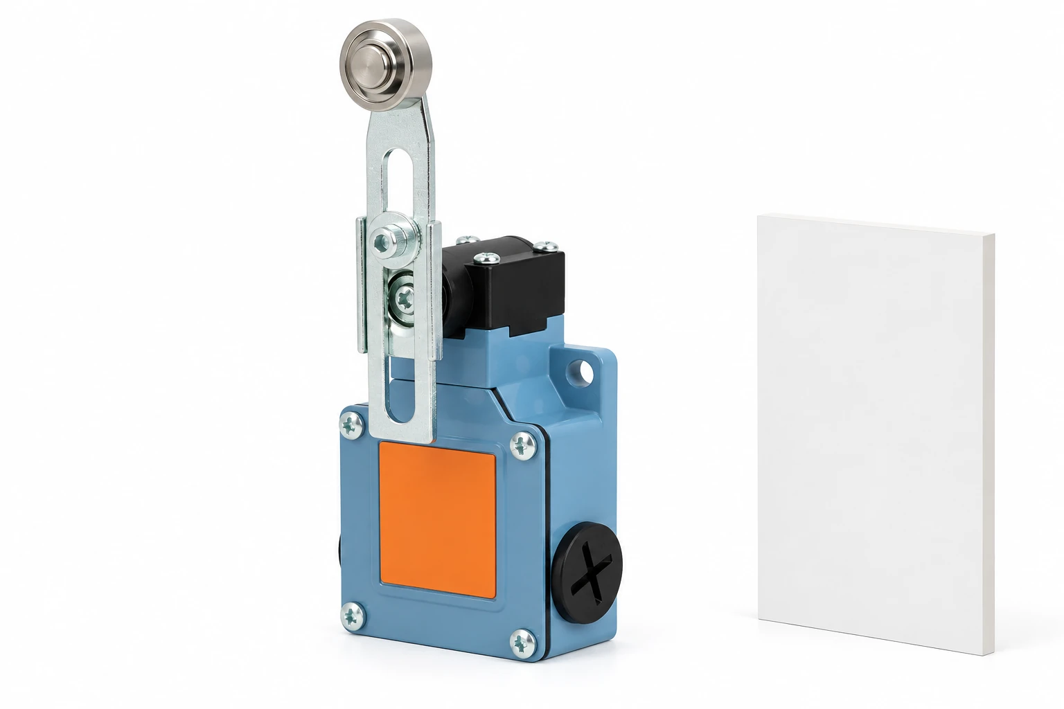
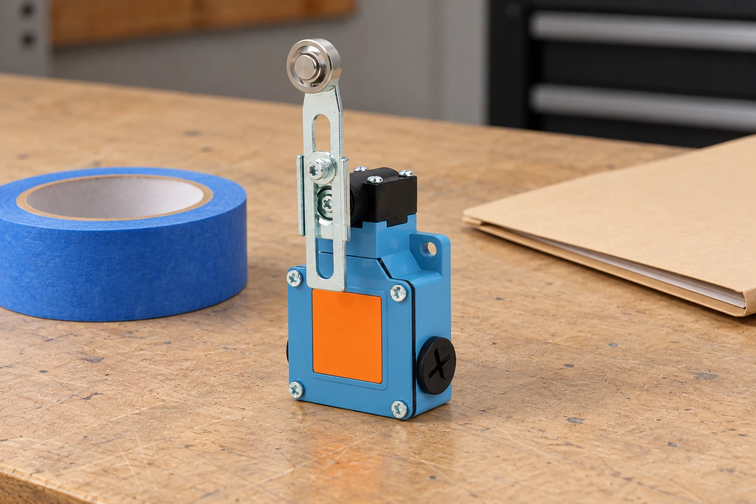
Le LEMA LZ1 series provides a real mechanical reference: the visible assembly includes the housing, head and lever arrangement. Identify the exact version and obtain the applicable product instructions. The family information does not establish compatibility with every coating line, solvent, protective film or improvised cover. Photographs here are product-reference illustrations; separate props do not represent an engineered guard or a qualified spray installation.
Compare protection options against the job
| Option to review | Potential benefit | Questions that remain |
|---|---|---|
| Install after painting | Avoid direct component exposure during coating | Can the assembly sequence preserve the released mounting design? |
| Relocate outside deposition path | Reduce exposure at the source | Will target geometry, access and wiring remain suitable? |
| Designed barrier | Interrupt the expected deposition route | Does it clear the full motion envelope and permit inspection? |
| Temporary isolated-work mask | Protect specified surfaces during authorized maintenance | How is removal verified before return to service? |
| Different approved device arrangement | Address unsuitable environmental conditions | Does exact equipment evidence cover the actual installation? |
Use this decision table to organize a design review, not as a universal endorsement of one method. A relocated switch may need a different target or bracket. A removable barrier may improve deposition control but require access and a reliable reinstatement process. A temporary mask used only during isolated maintenance is fundamentally different from a device left around a moving switch during production. State clearly which operating condition is being considered.
Avoid covering a working switch with a loose bag or wrapping tape around its lever. The concern is not simply whether paint is kept off the surface: the material may interfere with travel, retain contamination or hide a fault. Any proposed guard or barrier needs a documented assessment of its geometry, fixation, durability, access and effect on the machine. This article provides no drawing or dimensions that can substitute for that assessment.
Treat coating-process hazards as a separate boundary
Overspray prevention for a component is only one part of the job. The HSE guidance on isocyanate spraying describes substantial exposure concerns from spray processes and the need for suitable controls. It does not qualify a switch enclosure for use near a spray process. Use the site’s competent assessment for substances, ventilation, ignition risks and work practices before choosing electrical equipment or beginning maintenance.
Le CCOHS spray-painting guidance also emphasizes a process risk assessment and the information provided for coating materials. These sources support the need to review the work environment; neither gives an LZ1 solvent rating or an approved masking method. Obtain the actual coating and cleaner safety information and the component material guidance rather than treating the phrase water-based as a complete risk description.
For a location that may contain an explosive atmosphere, start with the hazardous-location limit switch review. An ordinary metal housing, low-voltage circuit or ingress rating is insufficient evidence of suitability. A shield around an unapproved device does not grant hazardous-location approval. The classification and protection arrangement need the exact equipment evidence required by the applicable installation assessment.
Preserve the baseline before maintenance
With the equipment made safe under its approved procedure, photograph the installed switch, target and cable route before disturbing them. Record the full part identifier, mounting position and relevant settings. Note any deposits already present and whether the actuator returns freely under the permitted inspection method. Do not force a stuck mechanism to create an apparently normal baseline; retain the observation for investigation.
Keep the mounting reference independent of the paint edge. A paint outline may not reproduce the original adjustment accurately, especially after surface preparation. If removal is authorized, store the component and its hardware so the original identity is retained. Record replacement parts separately. When the work is complete, the return-to-service check must confirm the function and installation rather than relying on matching a photograph alone.
Define what happens if contamination is found
Start with the manufacturer’s instructions for the exact component and the actual coating involved. Do not scrape a sealing surface, flood an enclosure with cleaner or apply an unverified solvent because it removes paint from a metal coupon. A cosmetic improvement may hide damage or carry contamination into the mechanism. If there is no approved recovery method, refer the component for a replacement decision through the maintenance process.
Document where contamination was found and what could have been affected. Separate deposits on an accessible external cover from material around a moving interface, cable entry or identification plate. Keep uncertainty explicit. A housing that looks clean after wiping is not evidence that the internal contacts remain unaffected. For systematic fault investigation, use the limit switch troubleshooting guide plutôt que de considérer un clic mécanique comme preuve de fonctionnement complet.
Vérifiez l’assemblage avant de remettre en service
Vérifiez que chaque élément de protection temporaire a été retiré ou placé dans son dispositif de fonctionnement approuvé. Confirmez l’identité du composant, la position de l’actionneur, la fixation et le dégagement de la cible par rapport à la configuration libérée. Inspectez le trajet de mouvement accessible pour détecter débris ou interférences. Si l’entrée du câble a été perturbée, inspectez-la selon les instructions d’assemblage correctes ; le cable gland selection guide explique pourquoi faire correspondre un filetage seul ne garantit pas un joint d’étanchéité complet à l’entrée.
Faites vérifier par le personnel qualifié responsable les états de contact pertinents et la réception d’entrée via la procédure de mise en service de l’équipement. Testez l’approche et le retrait normaux, y compris les conditions importantes pour le retour d’information de position. Maintenez les personnes à l’écart des mouvements dangereux et suivez le dispositif de test approuvé. Si une fonction de protection a été affectée, utilisez son processus de validation requis. Une vérification de continuité ordinaire ne constitue pas une validation complète d’une fonction de sécurité de la machine.
Enregistrez les résultats observés, la configuration et la personne ayant libéré le travail. Incluez toute modification des supports, surfaces cibles, câblage ou dispositifs de protection. Si le comportement de commutation a changé, arrêtez la mise en service et investigatez la cause plutôt que d’ajuster le logiciel pour dissimuler un mécanisme contaminé. Un rapport de remise en service doit expliquer ce qui a été vérifié et ses limites, et non simplement indiquer que la peinture a été terminée.
Fournissez au fournisseur les informations d’exposition dont il a besoin
Une enquête efficace nomme la version complète de l’interrupteur, le style de l’actionneur et la fonction de la machine. Ajoutez le processus de revêtement, la trajectoire de dépôt prévue, le contexte de température, le nettoyant pertinent et si une protection est nécessaire lors de la maintenance ou en fonctionnement normal. Fournissez un dessin montrant l’enveloppe de mouvement et l’emplacement proposé. Demandez des instructions documentées sur le matériau et l’installation, et identifiez toute preuve d’approbation requise pour l’environnement réel.
Ne demandez pas au fournisseur d’approuver une application dans une cabine de pulvérisation non définie à partir d’une photographie. Les propriétaires de l’équipement et du processus doivent résoudre l’installation complète. Si l’emplacement actuel accumule régulièrement des dépôts, utilisez cette preuve de maintenance pour revoir l’agencement et la séquence du processus. Nettoyer à répétition un levier qui colle est un signal pour investiguer la cause, et non une stratégie de contrôle à long terme démontrée.
Apprentissage supplémentaire : comprendre l’interface mobile
L’explication de RealPars ci-dessous présente le fonctionnement d’un interrupteur de limite mécanique ordinaire. Elle aide à identifier pourquoi l’actionneur et le trajet de la cible sont importants lors de la revue de la protection contre la surpulvérisation. Elle ne traite pas de la compatibilité du revêtement, de la conception d’un bouclier ou de la conformité aux zones dangereuses. Utilisez la vidéo pour le mécanisme de base, puis appliquez les instructions documentées du composant et l’évaluation de l’équipement à l’installation spécifique.
Limit Switch Explained | Working Principles | RealPars
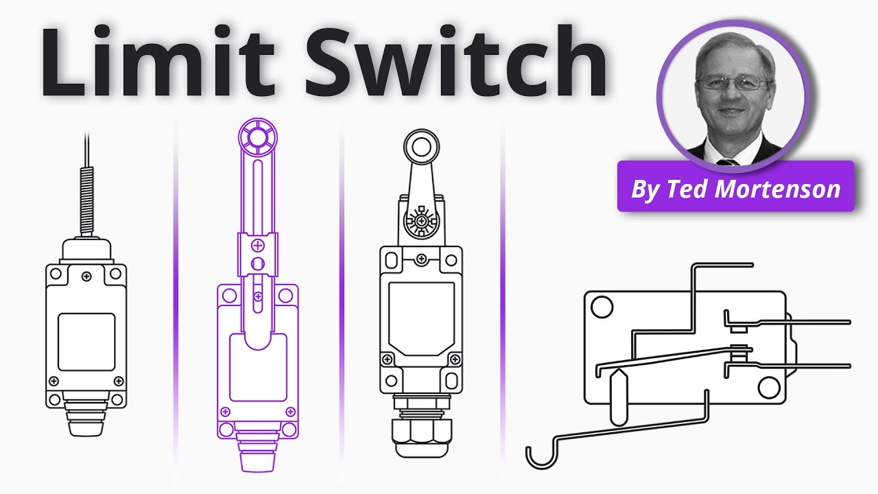
Watch Limit Switch Explained | Working Principles.
Foire aux questions
Un indice de protection IP garantit-il une résistance aux projections de peinture ?
Non. L’indice de protection ne permet pas, à lui seul, de déterminer l’accumulation du revêtement, la compatibilité avec les solvants ni le maintien du mouvement de l’actionneur. Examinez séparément le composant exact et son exposition.
Puis-je laisser un sac en plastique autour d'un interrupteur de limite en fonctionnement ?
Ne pas utiliser un sac en vrac comme couverture improvisée pour l'exploitation. Cela peut gêner le mouvement ou masquer une contamination. Une disposition de protection nécessite une évaluation documentée de l'ensemble de l'équipement et des conditions d'exploitation.
Peut-on utiliser n'importe quel solvant pour enlever la peinture séchée d'un interrupteur ?
Non. Suivez précisément les instructions relatives aux composants et aux matériaux approuvés. Si une méthode de récupération acceptable n'est pas disponible, utilisez le processus de maintenance contrôlée pour décider si un remplacement est nécessaire.
Ce guide approuve-t-il les interrupteurs LZ1 pour les cabines de pulvérisation ?
Numéro. Identifiez l'environnement réel, l'appareil complet et les exigences d'approbation applicables. Un boîtier ordinaire, un circuit basse tension ou une protection externe ne suffisent pas à établir la conformité pour les emplacements dangereux.