
Power inlet mounting flange flatness inspection begins by identifying the intended seating surface and the condition in which it must be checked. Examine the loose inlet and panel separately before tightening screws. Remove only permitted loose contamination, record rocking or visible gaps, and compare measurements with the approved drawing and agreed method. A flange that pulls down when screws are tightened has not automatically passed a flatness check. The assembly may be deforming to match the panel. Distinguish the inlet’s own form from panel distortion, surface obstruction and the fit of the complete mounted equipment.
Decide whether you are checking form or assembled fit
Flatness concerns the form of a defined surface. Seating concerns how two real parts contact in a particular arrangement. These questions overlap, but they are not interchangeable. A flat flange can sit poorly on a distorted panel, and an uneven flange can appear flush after forced assembly. State which question the inspection is intended to answer before selecting a fixture.
A mounting flange may contain ribs, recessed regions, molded features or local contact pads. Do not treat every visible exterior face as the intended mounting plane. Obtain the supplier drawing and identify the functional seating regions. If the drawing does not specify a flatness requirement, ask for the relevant assembly acceptance criteria rather than inventing a numerical limit.
Le IPZ series product page shows mounting variants. Confirm the exact screw-mount version before planning a flange check. A snap-in body has a different retention interface, so a procedure developed for screw ears should not be transferred without review. The mounting style comparison helps distinguish those interfaces.
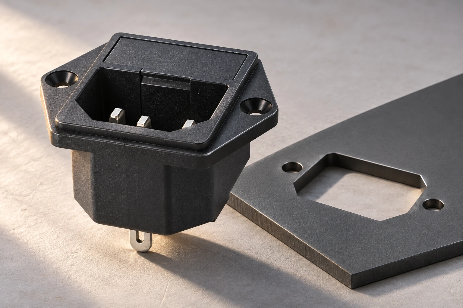
Check the panel before blaming the inlet
Look at the panel around the opening under suitable lighting. Record coating ridges, trapped debris, burrs, local dents and distortion near mounting holes. Check both faces where accessible and authorized. A localized obstruction can create the same visible gap as a form error. Record the as-received condition before any approved cleaning or correction changes the evidence.
Keep panel and inlet observations separate in the report. For example, “rocks on this enclosure panel” describes an assembly observation. It does not establish which part is out of specification. Compare with an appropriate controlled reference or approved fixture when required. A desk, packaging tray or piece of unknown glass is not automatically an adequate reference surface.
Utilisez le inlet cutout review for opening and hole-position questions. This article does not supply cutout dimensions or machining instructions. If hole position forces the inlet sideways before the flange contacts the panel, resolve that mismatch as an assembly problem rather than interpreting screw pull-down as a valid flatness measurement.
| Evidence item | Que vérifier | Decision supported |
|---|---|---|
| Defined surface | Drawing identifies the flange regions to inspect | The measurement concerns the functional interface |
| Part condition | Loose or constrained state is explicitly recorded | Results from different setups are not confused |
| Reference and support | Fixture condition and support points are documented | Rocking is not mistaken for a calibrated result |
| Panel condition | Burrs, coating and local distortion are recorded | The inlet is not blamed for a panel obstruction |
| Measurement method | Sampling locations, orientation and equipment are stated | A reviewer can repeat the check |
| Acceptance rule | Drawing or approved fit criterion is available | No unsupported universal gap limit is invented |
Choose a method suited to the actual geometry
A visual check can identify gross seating problems but has limited resolving power. A straightedge and feeler check samples particular locations and needs an agreed procedure. An indicator or coordinate method needs suitable support, surface access and a defined evaluation. The smallest displayed increment on an instrument does not establish that the entire measurement is accurate.
NIST’s surface and interface metrology group describes work on surface topography and measurement capability. That background supports the need to match the measurement to the surface. It does not provide an IPZ flange tolerance. Select the method with the responsible quality or design engineer, particularly where the part is compliant or difficult to support.
METAS describes optical flatness measurement for precision optical standards. That is an example of a specialized measurement system, not a recommendation to apply an optical-flat procedure directly to a molded inlet. Differences in surface finish, geometry and material can make a method inappropriate even when it is excellent for another kind of part.
Control support, clamping and orientation
A thin or compliant flange can change shape under handling or restraint. Record where the part is supported and whether anything is clamped. Avoid squeezing it into an apparently acceptable condition during inspection. If an approved fixture intentionally represents the installed state, call the result an installed-state assessment and preserve the fixture details. Do not present it as an unconstrained form result.
Orientation matters when comparing observations. Mark the part and panel orientation in photographs, then record where the gap or rocking occurs. A location description such as “right side” becomes ambiguous when the part is turned over. Use the drawing’s identification or an annotated inspection image so that the supplier can understand the same physical location.
Measure enough of the specified surface to support the decision. A single sweep or one edge check can miss a problem elsewhere. The sampling plan must come from the agreed inspection method, not from whichever path happens to be easiest to reach. If the relevant seating regions cannot be accessed reliably, request a different method or supplier evidence rather than declaring a pass from an incomplete check.
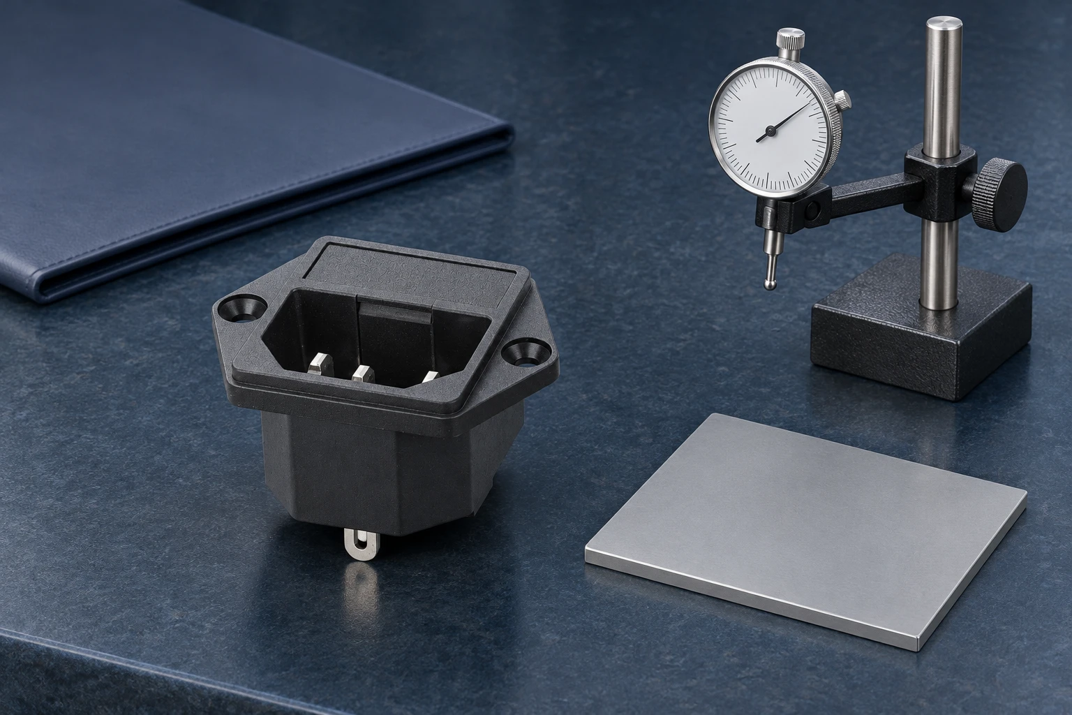
Do not use screw preload as a repair method
Tightening screws can change the contact pattern and may impose stress on the flange or panel. Follow the selected component and equipment mounting instructions. This article does not establish an installation torque, tightening sequence, washer arrangement or allowable gap. Those choices must be confirmed for the actual inlet variant, fastener and enclosure.
If seating requires unusual force, stop the trial and preserve the observations. Check for an incorrect mounting variant, mismatched hole position, coating buildup, obstructions or damaged parts. Do not file the flange, enlarge holes, add improvised packing or bend screw ears simply to make the assembly appear flush. Any modification needs an approved engineering disposition.
Visible cracking is a separate condition requiring its own assessment. The flange crack investigation guide addresses that evidence path. A seating check cannot establish the remaining strength of a cracked part. Similarly, an electrically functional inlet has not automatically passed mechanical mounting or finished-equipment safety review.
Write a report that separates observation from acceptance
A useful report identifies the inlet order code, lot, drawing revision, panel revision, inspected surface, support condition, equipment and method. Include photographs before installation and, where approved, after the mounting trial. Record the actual observations without replacing them with an unexplained “flat” or “not flat” label. Link the result to the acceptance criterion used.
When a number is reported, include the units, evaluation method and measurement limitations that affect the decision. Do not compare an indicator sweep from one setup with an optical result from another as though they measured the same quantity in the same way. Ask the laboratory or quality team to explain the relationship before using the results to reject a delivery.
For an OEM inquiry, send Lemaele the selected mounting version, panel material and thickness information, opening drawing, seating concern and photographs. Request the relevant mounting drawing and any applicable inspection guidance. Keep the full equipment inlet replacement review separate from this focused form check, because electrical rating, terminals and equipment compliance remain independent acceptance questions.
Separate screening from a conformity statement
Agree in advance whether the inspection is a quick assembly screen or a documented conformity measurement. A screen may identify parts that need further review without assigning a precise form error. A conformity statement needs a defined requirement, suitable measurement method and an agreed decision basis. Keep the original screening photographs even when a later measurement resolves the concern. If a part passes on one panel but rocks on another, record both panel identities and compare their conditions. That observation can help locate the source of the mismatch without assuming which component is responsible. It also prevents an unrecorded panel swap from making a disputed result impossible to reproduce.
Further learning
This NPTEL lecture explains geometric measurement concepts, including flatness. It supports understanding of the inspection question; it does not prescribe a tolerance, fixture or mounting procedure for an IPZ inlet.

Foire aux questions
Can tightening the screws prove the flange is flat?
No. Tightening can deform the interface. Record the initial condition and follow the approved mounting and inspection requirements.
What flatness tolerance applies to every IPZ inlet?
No universal flange flatness tolerance is established here. Confirm the exact variant, controlled drawing and agreed acceptance criteria.
Is a rocking inlet necessarily defective?
Rocking identifies a seating concern. Panel distortion, local obstructions, the support setup and inlet form must be distinguished before making a conformity decision.
Can a straightedge replace a complete measurement?
It can support a defined screening method, but coverage and limitations must be understood. Use the approved method when a quantified form result is required.