
A toggle switch for motor control may operate the motor directly only when the exact switch is documented for that motor’s voltage, current type, starting duty and switching conditions. Otherwise, a suitable relay, contactor or electronic motor controller can carry the power while the toggle supplies a command. Adding a relay does not automatically make the circuit suitable: its coil, contacts, protection and restart behavior still need review. This guide helps OEMs separate a maintained toggle command from the motor power path and prepare a complete design request.
Identify what the toggle is actually switching
Trace the circuit from the operator to the load. In a direct arrangement, motor current passes through the toggle contacts. In an indirect arrangement, the toggle may energize a relay coil or change an input on a motor controller. Those interfaces have different electrical demands, even when the same front-panel lever is used.
Record the supply voltage, AC or DC, motor type and intended operation. Starting, stopping, jogging and reversing are different duties. Include the expected operating frequency and the motor manufacturer’s starting information. Running current alone cannot describe the contact stress of starting a motor or interrupting an inductive circuit. Where the duty is unknown, obtain measured or manufacturer-supported data before selecting components.
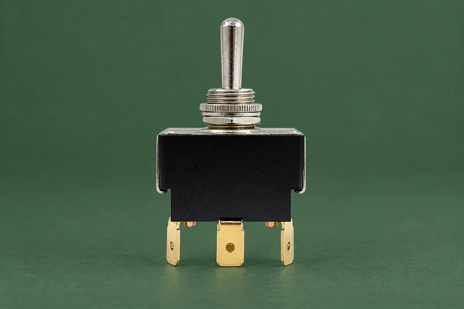
Do not interpret an AC resistive rating as a DC motor rating. Likewise, a headline current on a product photograph does not establish a utilization category or a permitted motor size. LEMA LT-series images identify a product family and visible construction. Approval for a particular motor circuit must come from the exact ordered variant’s electrical documentation and the equipment design.
Choose between direct switching and a command interface
Direct switching can be appropriate where a documented switch rating matches the complete motor duty and the equipment’s protection arrangement. It reduces the number of components, but the wiring and operator then carry the load current. The panel layout, terminals, conductor sizing and accessibility have to support that arrangement.
A relay or contactor separates the operator’s command circuit from the motor’s power contacts. This can simplify a control panel interface or allow additional control logic. However, the power device must be selected for its actual duty; a relay described only by a resistive ampere rating may be unsuitable for the intended motor. The coil also has an electrical load that the toggle must be allowed to switch.
An electronic controller introduces another interface. Its command input might require a dry contact, a powered signal or a defined enable sequence. Do not apply supply voltage to a contact-input terminal unless its documentation permits it. Confirm the controller’s input common, signal levels, timing and fault behavior before deciding that a general toggle can connect directly.
A decision table for the electrical design review
| Architecture | What the toggle carries | Evidence required | Additional review |
|---|---|---|---|
| Direct motor switching | Motor operating and switching current | Exact switch duty matching voltage, AC/DC and motor load | Starting conditions, protection, wiring and switching life |
| Relay or contactor command | Coil circuit load | Toggle coil-duty compatibility and rated power-device contacts | Coil suppression, release timing and restart logic |
| Motor-controller input | Specified command-interface signal | Controller input specification and suitable contact performance | Common reference, signal thresholds and allowed sequence |
| Reversing command | Direction request or separately approved power path | Controller or reversing-device design documentation | Interlocking, stopping conditions and prohibited simultaneous commands |
These are design questions, not ratings for the illustrated switch. IEC 60947-5-1 covers electromechanical control-circuit devices. Determine the applicable standards and selected component evidence for the finished equipment separately.
A maintained lever changes the restart question
A maintained toggle can stay in the ON position after control power disappears. When power returns, the circuit may request operation again without a fresh movement of the lever. Whether the motor actually restarts depends on the starter or controller logic. This behavior has to be reviewed against the machine’s intended operating sequence and risk assessment.
A momentary Start button in a conventional three-wire starter arrangement works differently from a maintained two-wire command. Do not replace one with the other because both can energize the same coil on a bench. Identify what clears the command, what resets a fault and what happens after loss of power. The operating instructions and panel markings should agree with the implemented behavior.
Test power restoration under the approved commissioning procedure. Record the lever position, controller state and motor response. If the required behavior is a deliberate restart, the control architecture must enforce it; a warning label does not change the circuit. An ordinary toggle also does not become a safety device simply because it controls a contactor.
Review coil transients without inventing a universal solution
A relay coil is inductive. When current is interrupted, stored energy can create a voltage transient across the circuit. Suppression must suit the coil supply and the equipment design. NI’s inductive-load switching guidance explains the underlying transient and examples of suppression for its relay applications; it does not specify a protection component for every motor panel.
Use the coil or controller manufacturer’s approved suppression arrangement. Check polarity where a DC protection device is used and check whether protection is already built into the coil assembly. Do not put a generic diode across an AC coil. The choice can affect release timing, so include the required response in the review rather than treating suppression as a purely cosmetic accessory.
The motor power path may need its own protection and switching measures. Coil suppression and motor overload protection address different problems. A functioning low-power command does not prove that the load contacts can start or stop the motor reliably. Keep the coil interface, power-contact duty and protective functions in separate acceptance fields.
Match terminal construction to the harness
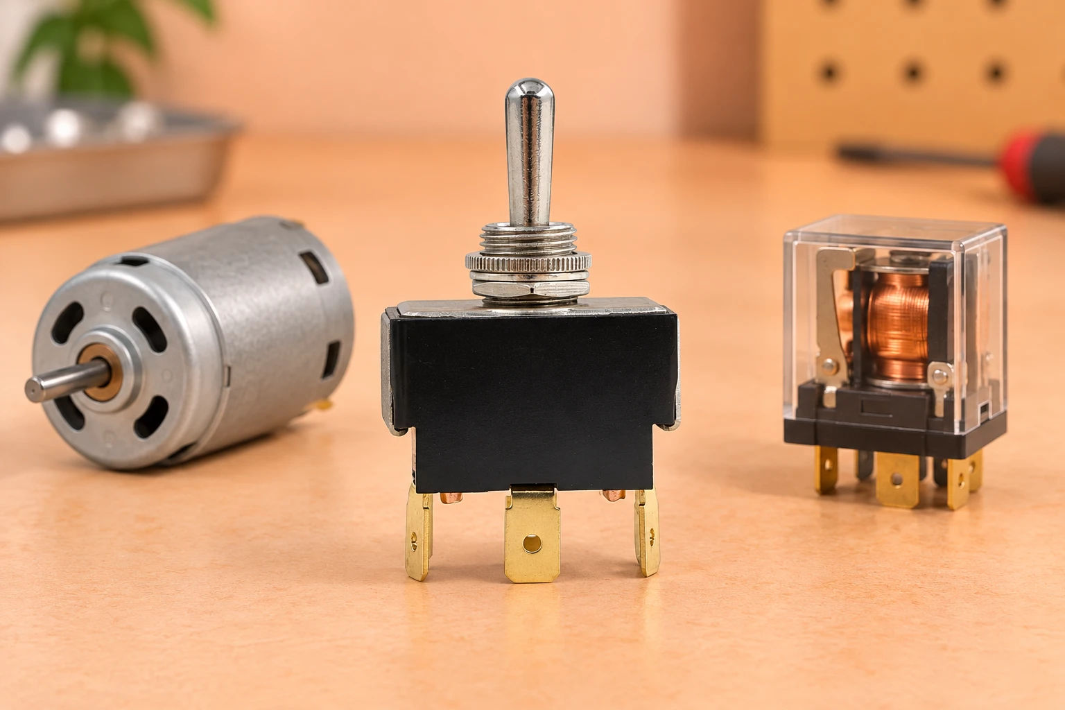
The reference LT-series product has a metal lever, a threaded bushing and flat terminal blades. That appearance helps identify the mechanical interface, but it does not identify terminal function. Obtain the contact diagram for the selected pole and throw arrangement. Check each state against the approved circuit rather than assuming the middle blade is always the correct common.
Use the specified mating terminals and installation process. Check conductor suitability, connector retention and clearance from adjacent metalwork. A push-on terminal that feels tight is not by itself a documented connection. The harness should avoid side loads on the switch and should allow installation without bending terminal blades to compensate for insufficient space.
Confirm that the switch fits the panel’s finished thickness and mounting opening. Preserve space for the connector and the wire bend behind the panel. Operator force should not rotate the body or strain the wires. Mechanical mounting is a parallel acceptance item; it cannot compensate for an unsuitable electrical duty.
Commission the command and power paths separately
Begin with the approved drawings, component part numbers and isolated checks. Confirm the toggle’s released or maintained states and compare them with the command logic. Verify that the relay, contactor or controller receives the intended command and that its power contacts or output stage match the documented load. Only authorized personnel should perform energized commissioning under the equipment procedure.
Check normal start and stop behavior, allowed direction changes, power-loss recovery and fault reset. Record expected and actual results for each state. Avoid repeated jogging or stalled operation as an improvised stress test. If the design permits a reversing command, verify its interlocking and stopping sequence using the manufacturer’s procedure.
Pour la maintenance, suivez le processus de contrôle d'énergie du site. OSHA’s hazardous-energy control standard distingue l'isolation d'énergie des dispositifs de contrôle ordinaires. Ouvrir une commande de bascule ne signifie pas que toute l'énergie dangereuse a été éliminée de la machine.
Préparez une demande de devis pour une commande de contrôle moteur
Envoyez l'architecture de contrôle exacte, l'alimentation du moteur et la charge, le comportement de la commande, la spécification de la bobine ou de l'entrée, la configuration des pôles/commutateurs, la préférence de terminal et les détails de montage. Demandez les valeurs spécifiques à la variante et le schéma de contact. Incluez le comportement de restauration de puissance et la fréquence de fonctionnement afin que l'opérateur proposé puisse être évalué dans le cadre de la conception complète.
Commencez par le LEMA toggle switch range et le Guide de sélection OEM pour les leviers métalliques de la série LT. Pour les questions connexes, lisez Contrôles de démarrage par bouton-poussoir momentané et Bascules maintenues versus bascules momentané. Ces sujets expliquent des interfaces complémentaires plutôt que de remplacer la revue de la charge du moteur.
Conservez l'architecture approuvée, les composants sélectionnés, la preuve du fournisseur et le registre de mise en service avec la nomenclature. Un remplacement ultérieur de commutateur, relais ou contrôleur devrait rouvrir les vérifications concernées. Cela évite qu'une démonstration réussie en banc ne soit confondue avec l'approbation d'un circuit de production différent.
Further learning
This independent educational video provides background for the checks discussed above. It does not identify the terminals of the illustrated LEMA product or replace the equipment manufacturer’s approved procedure.
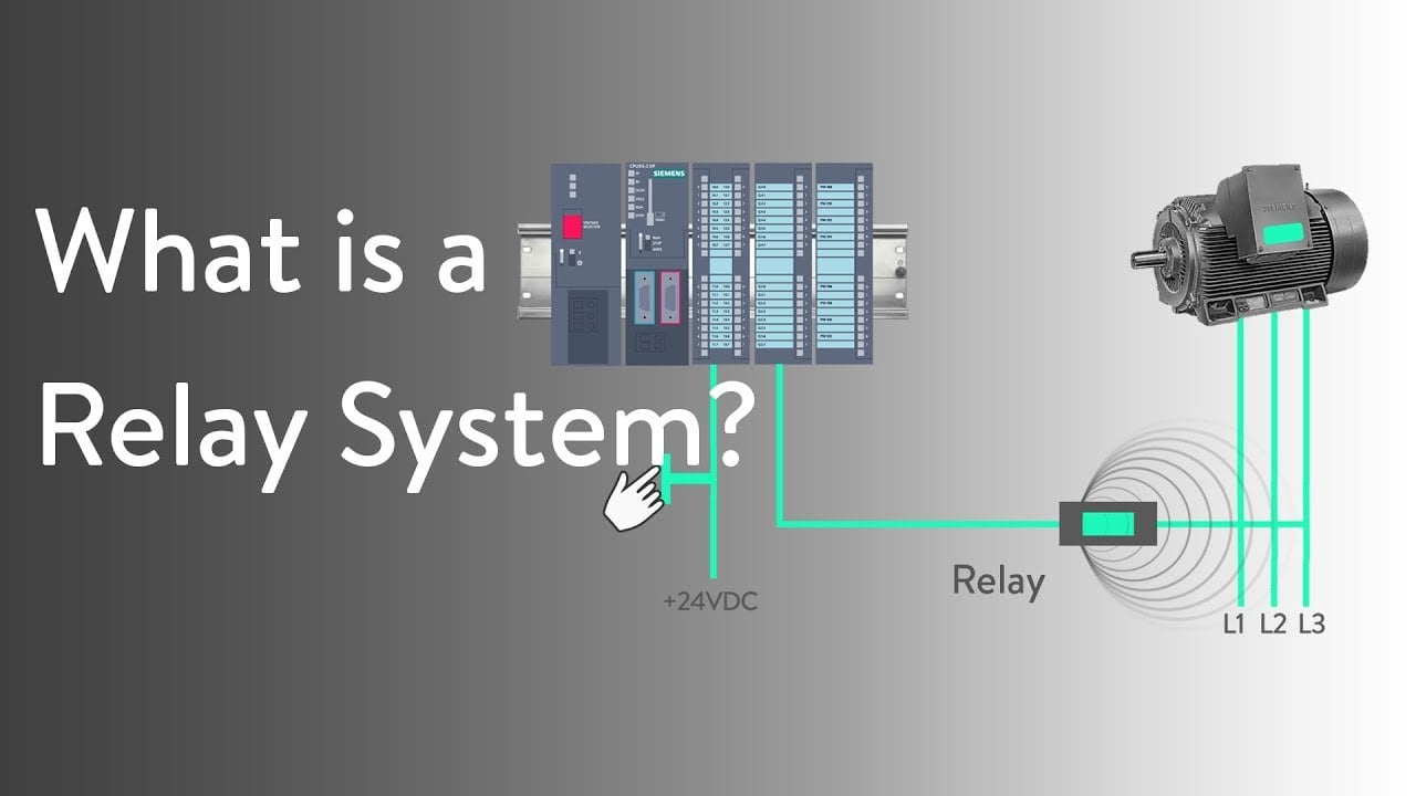
Watch What is a Relay System ? — RealPars
Foire aux questions
Un interrupteur à bascule peut-il commander directement un moteur ?
Uniquement lorsque la documentation exacte de l’interrupteur correspond à la tension du moteur, au type de charge (CA/CC), au régime de démarrage et aux conditions de commutation. Une intensité nominale en ampères indiquée uniquement pour une charge résistive ne suffit pas.
L'ajout d'un relais élimine-t-il tous les problèmes de notation ?
Numéro. Vérifiez la durée de vie de la bobine de commutation, la durée de vie du relais, le comportement de protection et de contrôle pour le circuit réel.
Pourquoi un interrupteur maintenu peut-il redémarrer un moteur après le retour de l'alimentation ?
Le levier peut conserver sa demande de marche. Le redémarrage réel dépend de la logique du contrôleur ou du démarreur et doit être vérifié par rapport au comportement requis de la machine.
Les positions des terminaux sur une photographie peuvent-elles définir le câblage ?
Non. Utilisez la variante exacte du schéma de contact et vérifiez les états prévus selon la procédure de test approuvée.