
A toggle switch mounting nut clamps the switch’s threaded bushing and hardware stack to the panel. A secure installation needs more than a nut that feels tight: the bushing, panel thickness, washers, thread engagement, tool access and resistance to rotation all have to match the exact model drawing. Use the manufacturer’s specified tightening method and torque where provided. Do not transfer a torque value from another switch or keep tightening until the panel, seal or switch body deforms.
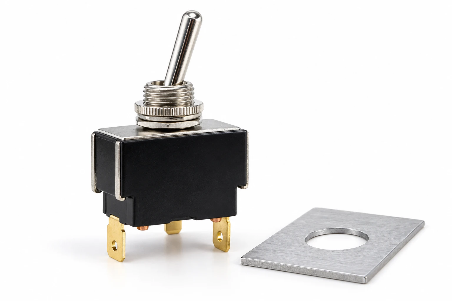
This guide concerns mechanical retention of a threaded-bushing toggle. The LEMA LT2210C product provides the visible product reference. The illustrations preserve its existing bushing, nut and washer; they do not add an unverified anti-rotation accessory or claim that a particular tool setting has been approved.
Identify the complete clamp stack
List the components between the switch body and the outer nut: panel, flat washers, sealing parts, locating hardware and any other manufacturer-approved pieces. Record their order and orientation from the controlled drawing. A stack assembled from visually similar spare hardware may not behave like the original.
Check that the panel is within the permitted thickness range. Added paint, an overlay, a gasket or a second backing plate can consume the available bushing length. The nut must engage as specified without bottoming on an unintended feature or leaving an unsupported stack.
Le panel cutout guide addresses hole geometry and clearance. Nut tightening is the next question: whether the actual stack can establish and maintain the required clamp without damaging the component or panel.
Verify thread and hardware identity
A nut that starts onto a thread is not automatically the correct hardware. Confirm the thread form and the approved nut and washer part numbers. Inspect for damaged threads, burrs, corrosion and contamination. Do not force a mismatched nut or use it to chase a damaged switch bushing.
A knurled nut, hex nut and decorative ring can require different tools or procedures. Avoid assuming that a hand-grip surface provides a defined tightening value. The component drawing or assembly instruction should identify the accepted method and any necessary holding arrangement.
Where replacement hardware is proposed, obtain approval for the actual combination. Changes in washer hardness, thickness or surface can alter the joint. A substitute nut that fits the thread can still change tool access, clamp distribution or available engagement.
Protect the switch while tightening
Plan how the switch is supported during assembly. The tool should act on the intended nut or holding feature, not on the lever, terminals or an unsupported plastic housing. Prevent the component from turning in a way that twists connected conductors.
Do not use the toggle lever as a handle to resist the tightening tool. That can apply an unintended load to the operating mechanism. Likewise, pulling on terminals to hold the body is not an acceptable substitute for the approved fixture.
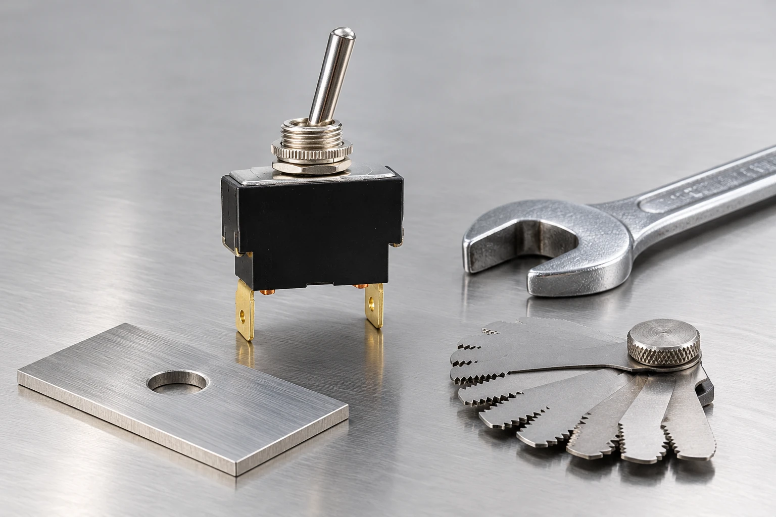
Tool access matters before the panel is populated. A wrench that only fits at an angle may contact adjacent devices, mark the panel or prevent a repeatable procedure. Review the rear clearance and assembly order with the actual enclosure, wiring and neighboring components in place.
Use torque information correctly
A specified torque belongs to a defined component and assembly condition. Check the unit, permitted range, tool method and any assumptions about the hardware. Do not confuse a maximum permissible torque with a target value unless the instruction explicitly says how it should be used.
If no value is published, request the current assembly guidance. Do not calculate a switch-nut value solely from a generic bolt chart; the bushing, housing, panel and sealing stack may govern the limit. The OpenStax explanation of torque provides mechanical background, not a product tightening recommendation.
For a production process, identify the tool and its control method. Where torque is an acceptance characteristic, maintain the appropriate calibration and process records. A statement that an assembler used a small wrench does not establish a repeatable result.
Check rotation separately from apparent tightness
The assembly needs to resist the motion and loads defined for the equipment. A nut may appear seated while the switch body can still rotate because the stack is incorrect, the panel is too flexible or the locating arrangement is ineffective. Evaluate that behavior using an approved inspection method.
Do not invent an anti-rotation tab or washer for a model that has no confirmed provision for it. Review the actual drawing and any approved locating features. If the design needs a keyed panel or special hardware, that requirement has to be supported by the selected model and manufacturing drawing.
Record the intended lever orientation before checking retention. Rotation can change labels, operating direction and wire clearance even when the electrical contacts still function. The mechanical acceptance should therefore include the installed orientation and its permitted movement.
Keep sealing and clamping requirements distinct
A sealing washer may also sit in the clamp stack, but it is not simply an extra flat washer. Its material, position and compression requirements need to match the approved assembly. Excessive compression or an uneven panel surface can defeat its purpose.
Le sealing-washer guide discusses environmental interface questions. The IEC 60529 catalogue identifies enclosure protection requirements; it does not prove an assembled panel’s rating or supply a nut torque.
Do not add sealant, lubricant or thread-locking material without approval. These materials can change the joint condition, affect plastics or seals and complicate service. If a retention aid is required, identify the exact material, location and process in the assembly instruction.
| Vérifier | Enregistrement | Reject or clarify when |
|---|---|---|
| Hardware stack | Part identity order orientation and thickness | Extra or substituted parts lack approval |
| Thread engagement | Specified thread and available bushing length | Nut is mismatched damaged or bottomed |
| Tool method | Approved holding and tightening arrangement | Lever terminals or housing take unintended load |
| Panel support | Flat seating and permitted material thickness | Panel distorts or overlay settles unpredictably |
| Retention | Orientation and allowed movement | Body rotates or wiring is twisted |
Inspect the panel and the rear clearance
Look for burrs, distorted edges, uneven coatings and a panel that bends under the clamp. Confirm that the switch seats on the intended surface rather than on a nearby interference. A soft overlay can settle after assembly and change the clamp condition.
À l'arrière, vérifier l'espace libre avec les bornes et conducteurs lors du mouvement complet du levier et de la manipulation prévue. Un interrupteur solidement maintenu peut toujours être inacceptable si l'orientation du corps force le câblage contre le bord d'une enceinte. La revue du montage appartient à la vérification de l'espace électrique et du faisceau.
Le guide d'approvisionnement pour interrupteur à bascule aide à organiser les documents du modèle nécessaires avant d'accepter un autre manchon ou arrangement de matériel. Comparez la preuve de montage réelle dans le cadre de la décision d'achat complète.
Définir une séquence d'assemblage et de réinspection
Avant le câblage ou la mise sous tension de l'équipement, confirmer l'identité du composant, l'état du panneau et la séquence du matériel. Installer l'interrupteur dans son orientation requise, appliquer la méthode d'immobilisation et de serrage approuvée, et inspecter le joint terminé. Enregistrer tout résultat de couple ou de retenue requis.
Vérifier le mouvement complet de l'actionneur et son comportement de retour si applicable. Rechercher des changements causés par le serrage, tels que des interférences ou une déformation du boîtier. Inspecter les bornes et conducteurs après serrage pour confirmer que la manipulation de l'assemblage n'a pas transféré de charge vers eux.
Une inspection de service doit suivre la procédure de contrôle d'énergie de l'équipement. Le guide de l'OSHA sur l'énergie dangereuse explique pourquoi un interrupteur de contrôle ne peut pas être considéré comme la méthode d'isolation lors de la manipulation de son montage ou de son câblage.
Rendre le dossier d'approvisionnement reproductible
Spécifier le code de commande de l'interrupteur, le dessin du panneau, l'épaisseur autorisée, la finition, les numéros de pièce du matériel, l'ordre de pile, l'orientation et la méthode d'assemblage approuvée. Inclure l'accès aux outils et toute caractéristique de localisation. Si un couple est spécifié, en préserver l'unité et la plage exactement.
Pour un substitut proposé, comparer le manchon et la pile de serrage aussi soigneusement que la capacité de courant de contact. La correspondance du diamètre du trou ne garantit pas la même capacité d'épaisseur de panneau ou l'agencement du matériel. Demander le dessin contrôlé et résoudre les différences avant la production.
Envoyer les détails du panneau et du montage via le LEMA contact page. Un enregistrement d'installation clair permet une discussion utile du joint fileté réel plutôt qu'une demande générale pour un écrou “ suffisamment serré ”.
Apprentissage supplémentaire : charge et déformation
Khan Academy India – Anglais : Stress & déformation | Classe 11 (Inde) | Physique | Khan Academy. Khan Academy explique le stress et la déformation. Ceci est un contexte pour comprendre la déformation dans un panneau serré ; il ne prescrit pas le couple de l'écrou de l'interrupteur à bascule ni ne prouve un assemblage de montage.
Watch Stress & strain | Class 11 (India) | Physics | Khan Academy.
Foire aux questions
Quel couple de serrage dois-je appliquer à chaque écrou de fixation à bascule ?
Il n’existe aucune valeur universelle. Procurez-vous la notice complète de montage du modèle et vérifiez l’empilement des éléments de fixation, le panneau ainsi que les conditions spécifiées. Un tableau générique de couples de serrage ou la documentation d’un autre modèle d’interrupteur ne permet pas de déterminer la valeur correcte.
Puis-je maintenir le levier tout en serrant l'écrou ?
Ne pas utiliser le levier de commande comme dispositif de maintien improvisé. Utilisez le support ou la fixation approuvés par le fabricant afin que le serrage ne transmette pas de force indésirable dans le mécanisme, le boîtier ou les bornes électriques.
Une écrou serré prouve-t-il que le panneau est étanche ?
Le numéro de scellement dépend du joint approuvé, de la pile, de la surface du panneau et des conditions d'assemblage. La fixation mécanique et la protection du boîtier sont liées mais distinctes, et une compression excessive peut endommager l'interface prévue.
Une écrou de rechange à filetage unique peut-il remplacer l'original ?
L'ajustement du filetage n'est qu'une caractéristique. Confirmez les dimensions approuvées, la combinaison de rondelles, l'engagement, le matériau et la méthode d'outil. Un substitut peut modifier la répartition de la pince ou la longueur de montage disponible malgré l'ajustement du filetage.