
Replace the complete function, not only the visible button
A push button switch replacement must preserve the original action, contact arrangement, panel fit, electrical duty and terminal system. If the button is illuminated, the indicator circuit also needs a separate comparison. A similar cap color or the same number of pins does not establish compatibility. Start with the equipment instructions and complete original order code, then compare a current drawing and contact diagram for the candidate. This guide focuses on equipment panel controls and OEM substitution checks; it does not authorize changes to emergency stops, safety interlocks or proprietary service assemblies.
O Gama de botões de pressão LEMA offers product families to review against an application specification. Product photographs can help identify external features, but they cannot prove a contact circuit, cutout dimension or approval. The replacement needs a documented comparison and a defined acceptance test before it enters service.
O industrial push button selection guide provides the broader application framework. Use this replacement checklist to compare the original assembly and candidate against that specification, rather than choosing a new circuit function.
Decide whether the actuator, contact assembly or entire unit needs replacement
Confirm the fault before ordering parts. A jammed cap, damaged contact, loose terminal and failed indicator can produce different symptoms. Use the complementary push button troubleshooting guide to separate those faults. A wiring defect or incorrect control-input configuration will not be corrected by installing a new button.
Some panel controls use separate actuator and contact blocks; others are supplied as an integrated assembly. Follow the manufacturer’s service instructions. Do not assume contact blocks from different series fit together because their clips look similar. A mechanical attachment can appear secure while failing to transmit the required movement or preserve contact timing.
If the button forms part of a protective function, determine the exact approved assembly and verification requirements. Replacing an ordinary control with a red or mushroom-shaped actuator does not establish an emergency-stop function. Hold undocumented substitutions where the equipment’s required safety behavior cannot be confirmed.
Record the original installation and markings
Photograph the front and rear after isolating the equipment under its maintenance procedure. Record the complete order code and suffix, cap shape, operator action, contact diagram and terminal markings. Note any keying, locating feature, protective cap, legend plate or retaining hardware. A partial part number may omit the contact arrangement or illumination option.
Label conductors with their circuit and terminal designations before disconnecting them. Distinguish contact wires from indicator supply wires and note any shared common required by the original diagram. Wire color and pin count are supporting observations, not reliable circuit identification. Save the drawings and photographs with the replacement comparison.
Check the panel condition as well. A damaged cutout, cracked mounting area or strained cable can compromise a new component. Record panel thickness and rear clearance from the equipment drawing or a competent measurement procedure. Do not enlarge a panel hole as a routine workaround for an incompatible switch.
Match momentary, maintained and release behavior
A momentary button changes its contact state while operated and returns when released. A maintained button retains its state until another specified action changes it. The replacement must preserve the behavior required by the circuit. A maintained substitution can leave a command active after the operator expects it to stop, while a momentary substitution may fail to retain a selected mode.
Write the required circuit state for released, pressed and returned conditions. For maintained operation, include every latch and unlatch state. The actual machine response can depend on controller logic, so check the equipment signal as well as the switch contact. The momentary versus maintained push button guide explains the difference without assuming the machine logic.
Confirm that any mechanical reset method matches the original instructions. Do not replace a twist-release, key-release or other special actuator with a general button based only on a mounting dimension. The operator interface and the control function must be reviewed together.
Compare NO, NC and contact combinations
Normally open and normally closed refer to the stated unactuated contact condition. Determine that reference condition from the exact diagram, especially for maintained or multi-contact assemblies. Compare each contact independently and record which circuit it serves. A multi-contact assembly may use one circuit for a command and another for feedback or monitoring.
Do not assume that two visible contact terminals identify the full function of an illuminated switch. Additional pins may belong to the lamp, and a shared connection can vary by model. The push button contact-block guide is a complementary reference for contact functions and compatibility. Use the replacement diagram as the final authority for pin identification.

| Replacement check | Prova necessária | Reason to stop and review |
|---|---|---|
| Ação do operador | Released, pressed and latched-state description | Command duration or reset method changes |
| Contact function | Exact NO/NC diagram for every contact | Required command or monitoring contact is missing |
| Panel interface | Cutout shape, dimensions, thickness and locating features | Fit requires panel modification or force |
| Dever elétrico | Voltage, AC/DC, load and contact material specification | Only the headline current value has been compared |
| Indicator | Supply voltage, polarity and internal circuit | Lamp circuit or shared connection is unidentified |
| Conexão | Terminal geometry and approved mating system | Connector retention or cable clearance is inadequate |
This qualitative table organizes the comparison. It does not supply universal cutout dimensions, electrical limits or mounting tolerances; those belong to the exact drawings and equipment specification.
Verify the cutout and rear mounting space
Compare cutout shape and dimensions, permissible panel thickness, retaining arrangement and any anti-rotation feature. A nominal family size is not a complete mounting specification. Check the drawing orientation and tolerances, and ensure the mounting method supports the required sealing boundary. An oversized hole can leave a button apparently fixed but incorrectly retained.
Inspect the rear envelope with the connectors and conductors installed. Allow enough space for the specified mating parts and cable routing without pulling on contacts or blocking moving parts. A compact replacement may still need more clearance for a different connector orientation. If a contact block is removable, confirm that it can be inspected and serviced under the equipment maintenance arrangement.
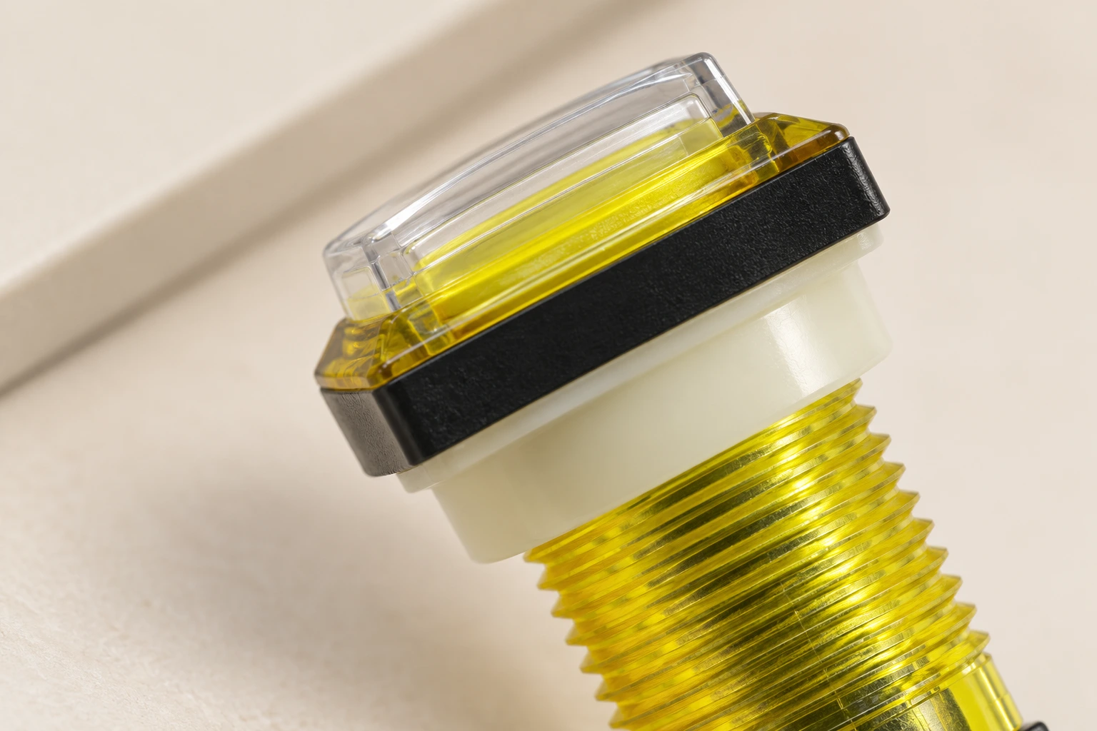
The illustrations use the real LEMA PBS reference with a clear cap, translucent yellow threaded barrel and lower contact assembly. They show external identification and mounting features, not a verified pinout or measured cutout. Do not infer an indicator function from the translucent parts or assume every PBS variant has identical contacts. Ask for the current exact-model drawing.
Compare contact duty and indicator supply separately
Identify whether the contacts switch a controller input, a relay coil or a direct load. Compare voltage, AC or DC, load category and relevant rating conditions. A resistive rating does not automatically establish an inductive duty, and a large current number does not establish suitability for a low-current signal. Match the selected contact material and the actual circuit conditions.
For illuminated versions, compare the indicator supply independently of the contact rating. Confirm AC/DC compatibility, required polarity and any internal resistor or electronics shown in the supplier diagram. Do not connect a lamp pin to a contact circuit based on a generic five-pin drawing. If the original uses a separate indicator supply, preserve that separation unless an approved redesign specifies otherwise.
Investigate heating, arcing or a failed indicator before accepting a substitute. A loose connection, incorrect supply or unsuitable duty may damage the replacement as well. Retain specified suppression and switching interfaces. Any circuit change must be reviewed for its effect on the equipment, rather than treated as a connector adaptation.
Control energy and validate the complete response
Follow the equipment’s isolation procedure before working on the button or wiring. The OSHA hazardous energy guidance addresses unexpected startup and stored energy during maintenance. Pressing a stop button or placing a selector in off must not be assumed to provide the isolation required for service.
On an isolated contact circuit, verify the expected states and release behavior against the documented table. Account for parallel circuit paths. A continuity check can establish contact behavior under the test conditions; it cannot prove load endurance, insulation or a safety function. Inspect mounting, terminal retention and cable strain before any authorized operational test.
Then use the equipment commissioning procedure to confirm the actual input signal, indicated state, intended action and required restart behavior. The HSE machinery maintenance guidance supports competent maintenance with suitable instructions and records. For a protective function, complete the applicable engineering validation before returning equipment to service.
The RealPars educational video below explains testing digital control inputs and outputs. It helps show why contact movement must be distinguished from the signal received by a controller. Apply only the portions appropriate to an authorized test plan; the video is not a service instruction for your equipment.
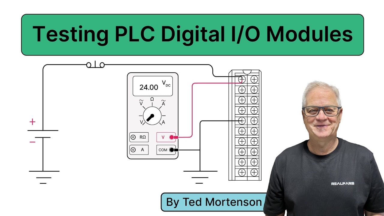
Watch the RealPars control-input explanation on YouTube.
Send a complete substitution request
Provide the original order code, circuit diagram, required action, panel drawing, terminal photographs, load conditions, environment and indicator requirements through LEMA’s contact page. Include annual quantity, approval needs and traceability requirements. Ask for a requirement-by-requirement comparison instead of a general “equivalent” statement.
Retain the approved part number, drawing revisions, accepted differences and test results. Update the production bill of materials and assembly instructions when a substitution is adopted. If a critical requirement cannot be established, keep the original approved specification and hold the replacement.
Perguntas frequentes
Can a same-color push button replace the original?
Color alone does not establish function. Compare action, contacts, mounting, electrical duty, indicator circuit and equipment requirements before accepting the substitution.
Can I reuse another series’ contact block?
Only when the manufacturer documents that compatibility for the exact parts. Similar clips do not prove correct retention, movement transmission or contact timing.
Does matching the number of pins prove the wiring is the same?
No. Pins can serve contacts, an indicator or shared circuits in different arrangements. Use the exact model’s contact and indicator diagram.
Can this checklist approve an emergency-stop replacement?
No. An emergency-stop function requires the exact system requirements, component suitability and appropriate validation. Hold an undocumented substitution and follow the equipment’s approved service instructions.