
A push button switch current rating applies to a defined electrical duty, not to every load drawing fewer amperes. Match the exact contact’s voltage, AC or DC conditions, load type, making and breaking duty, operating frequency and installation conditions. A resistive rating does not automatically approve a motor, solenoid or electronic power supply. A high-current contact is also not necessarily the best choice for a low-level controller input. This guide explains how to collect and compare those requirements before purchasing a push button or approving a component substitution.
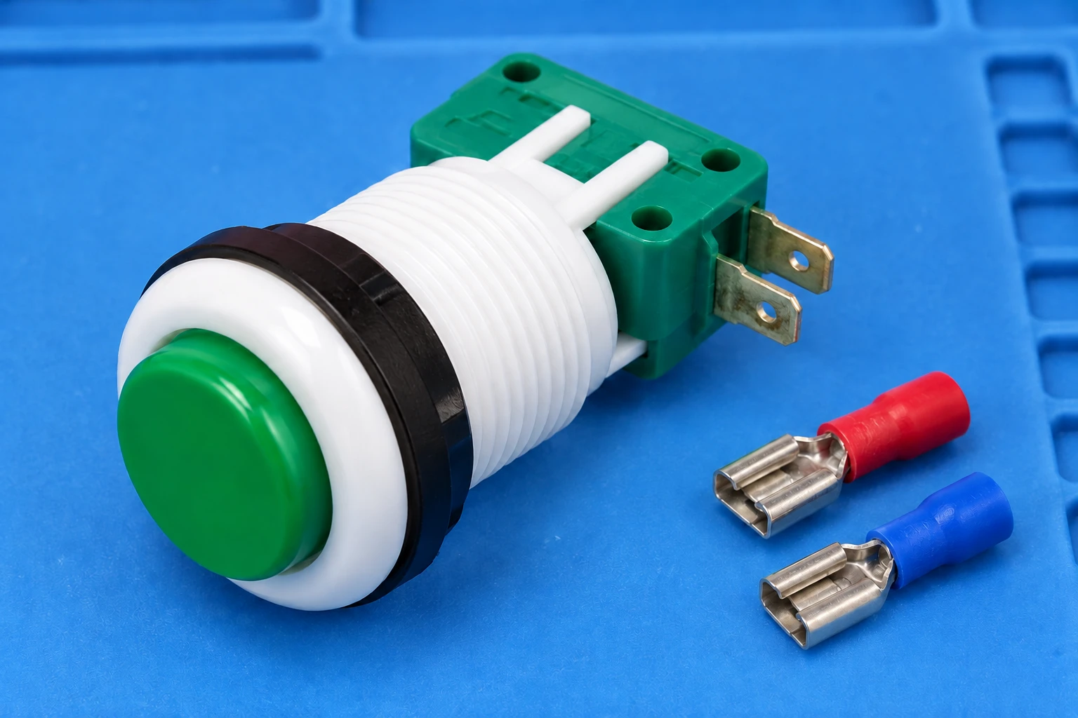
The focus is contact-load compatibility for equipment controls. Mechanical operation, button colour and terminal count remain separate selection questions. The pictured LEMA PBS-001 button is a physical product reference; no current, voltage or protective-function rating is inferred from its appearance. Electrical measurements and circuit modifications belong to qualified personnel using an approved equipment procedure.
Identify what the button actually switches
Begin at the schematic. A button may connect directly to a load, operate a relay coil, signal a controller input or perform another defined function. Those arrangements can place very different demands on the contact. Record the electrical component immediately downstream of the button rather than assuming that the machine’s motor power flows through the operator control.
Trace the actual contact circuit independently of any lamp circuit. An illuminated button can have separate terminals and supply conditions for its indicator. A lamp specification does not describe the switching contact. Equally, the presence of several terminals does not establish a particular internal diagram. Use the drawing for the exact order code and confirm its contact arrangement.
O industrial push button selection guide provides the broader mechanical and functional context. This article concentrates on the load record and the rating evidence. Keeping that distinction helps purchasing teams ask a precise question rather than requesting a button that is simply described as heavy duty.
Separate current carrying from making and breaking
A closed contact carries current through a conductive path. Making the circuit and interrupting it introduce additional conditions. The required current at closure, the current interrupted at opening and any associated transients can differ from the normal running current. A carrying value therefore cannot be used as a switching value unless the component documents explicitly support that interpretation.
NI’s technical explanation of carrying and switching current illustrates this distinction for switching systems. Its examples concern NI equipment; they are used here to explain terminology, not to transfer ratings to a manual push button. The final selection must use the button manufacturer’s applicable contact specification.
Record the sequence too. A button used only while a load is already disabled has a different documented duty from one expected to interrupt that load directly. However, a normal operating sequence does not justify ignoring foreseeable conditions specified by the equipment requirements. Have the circuit designer define the duty rather than treating an operator instruction as an electrical rating.
Compare resistive, inductive and electronic loads
| Load or interface | Information to obtain | Erro comum na seleção |
|---|---|---|
| Resistive load | Applicable AC or DC voltage, switching current and specified operating conditions | Using the largest printed number without checking its voltage or duty |
| Relay or solenoid coil | Coil demand, interruption transient and approved suppression arrangement | Assuming a modest running current eliminates inductive stress |
| Motor circuit | Actual switching arrangement and documented making and breaking requirements | Using motor running current as the only selection input |
| Electronic power input | Startup waveform and approved interface conditions | Treating a steady power consumption figure as the startup requirement |
| Controller signal input | Input current and voltage, contact compatibility and minimum load where specified | Choosing a power contact solely because its maximum current is high |
The table is a decision checklist, not a derating formula. For inductive switching, NI’s inductive-load explanation describes stored-energy transients and contact protection. It does not establish a universal suppression design for every circuit. Select protection with the load and switching-device documents, including any effect on the equipment’s operating behavior.
Do not use a fixed percentage of a resistive rating to invent an inductive or DC rating. If the needed duty is absent from the datasheet, obtain written evidence for that exact application or select a documented alternative. The absence of a rating is a missing decision input, not proof that a smaller load is acceptable.
Keep AC and DC evidence separate
A voltage and current pair should be read as a pair. An AC line on the component record is not interchangeable with a DC line. Contact interruption conditions differ, and the selected rating must match the circuit actually being switched. Avoid combining a high voltage from one declaration with a high current from another.
For illustration, a hypothetical datasheet might list two separate duties. A purchasing comparison should preserve both original lines, their load descriptions and their conditions. It should not collapse them into a single maximum voltage and maximum current row. That simplified spreadsheet can make an unsupported combination appear approved.
If the button operates a relay coil, confirm whether that coil is AC or DC and whether its suppression is included or external. A relay isolates the control circuit from the load switching function, but its coil still places a defined demand on the button. For the circuit arrangement, see the complementary push button motor starter guide.
Do not overlook low-level contact compatibility
A controller input can require relatively little current, yet it still needs dependable contact behavior. Check whether the proposed contact is specified for that signal level and environment. A larger maximum current number does not answer the minimum-load question. Different contact constructions and application conditions can behave differently at low levels.
O NI switch specification glossary includes minimum switching capacity among the parameters that may need review. It explains the term for its own relay products. For the actual push button, request the relevant low-level contact data rather than borrowing a minimum current from a different device.
Keep controller-interface requirements separate from contact timing. A signal may be electrically compatible while the input still needs to handle mechanical transitions. The push button debounce guide addresses that timing issue. Neither a debounce setting nor a successful initial controller response establishes long-term contact-load suitability.
Check the harness and terminal version
Current passes through the complete assembled connection, including the wire, mating terminal and contact. Compare the button’s terminal construction with the approved harness. Request the correct mating hardware and assembly instructions for the exact part. A quick-connect blade and a solder terminal are not interchangeable assembly details, even when the front actuator looks identical.
Review conductor routing, retention and insulation clearance. The design should allow the contact connection to be made and inspected without forcing the wire or bending the terminal to clear a cover. Do not invent a torque, wire size or crimp requirement from a photograph. Those values must come from the applicable drawing and specified accessories.
O referência de produto LEMA PBS helps identify visible actuator and housing styles. Ask for the drawing and electrical rating documents covering the offered order code, colour, operation and terminal variant. The product illustrations in this article intentionally show disconnected components and do not assign a function to an unidentified terminal.
Use measurements to describe the load, not to certify the button
Measurements can help establish normal current, startup behavior and operating sequence when made with an appropriate method. They cannot create an absent component rating. Record the instrument, measurement location, operating mode, supply condition and waveform information needed for the review. A meter’s display may not capture every short transient relevant to a switching duty.
For a simple resistive example, I = V/R connects voltage in volts, resistance in ohms and current in amperes. A hypothetical 24V source across a 240-ohm resistance gives 0.1A. This is an arithmetic example only. A coil, controller input or electronic load may not be adequately represented by that simple resistance, and the calculation does not approve any pictured switch.
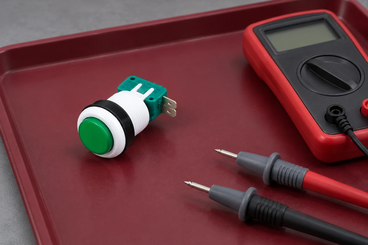
An isolated continuity check can confirm an expected state under its test conditions. It does not establish current rating, insulation performance or suitability for repeated load interruption. Use the separate push button multimeter test guide for those diagnostic boundaries. The final engineering acceptance still needs the correct component evidence.
Prepare an OEM request and an approval record
Give the supplier the actual circuit role, AC or DC voltage, normal current, known startup or interruption conditions, operating frequency and environment. Include required contact states, mechanical operation, mounting and termination. Ask which documented rating covers that duty and whether additional application conditions or contact protection are required.
Retain the response with the exact order code and document revision. If a proposed substitution changes the contact material, terminal version or internal construction, compare the relevant evidence again. A familiar button colour or unchanged front diameter is insufficient to approve the replacement. Purchasing needs a clear escalation route for a missing rating rather than silently substituting the nearest catalogue item.
Close the review by connecting the schematic role, measured or documented load, component rating and assembly record. State any remaining uncertainty plainly and hold that decision until it is resolved. Reliable selection comes from matching a complete declared duty to a complete application record, with the operator control and load-switching device each evaluated for the job they actually perform.
Further learning
This independent educational video provides background for the checks discussed above. It does not identify the terminals of the illustrated LEMA product or replace the equipment manufacturer’s approved procedure.
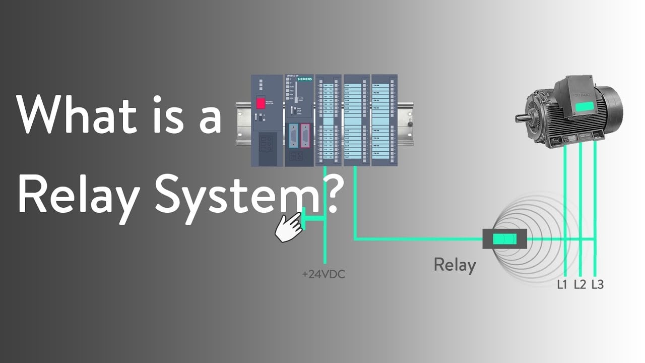
Watch What is a Relay System ? — RealPars
Perguntas frequentes
Can a resistive current rating be used for a relay coil?
Not automatically. Identify the coil, its AC or DC conditions and the applicable inductive switching and protection evidence for the exact contact.
Is carrying current the same as switching current?
No. Carrying describes the closed path, while making and breaking involve additional electrical conditions. Use the rating that covers the intended duty.
Is a higher-current push button always better for a PLC input?
No. Verify low-level contact compatibility and minimum-load conditions where specified, as well as the input voltage and current.
Does a multimeter continuity test prove the current rating?
No. It checks contact state under limited test conditions. It does not establish load switching, insulation performance or an absent component rating.