
A micro switch tolerance stack-up checks whether the assembled mechanism will operate the switch and let it return across the dimensional variation allowed by the design. Start from a common reference and track the dimensions between the switch mounting location and the moving target. Compare the resulting actuator position with the exact variant’s supported operating, travel and return requirements. Nominal alignment is only one case. An assembly can work at the center of its dimensions while another permitted combination fails to operate or imposes excessive travel.
Define the two states the mechanism must achieve
Write down the required mechanical and electrical conditions in both the target-present and target-withdrawn states. The required event may be a change in one contact path, but the assembly also needs a supported mechanical position and an unobstructed return path. Identify which machine position establishes each state and what controls that position. A loosely described requirement such as ‘press the switch fully’ leaves both the actuation boundary and maximum imposed movement undefined.
Utilize KW7 product family only as the starting point for obtaining the exact component documents. Confirm the complete actuator variant, mounting features, contact arrangement and drawing revision. The travel definitions article explains why pretravel, overtravel and differential travel address different boundaries. Do not replace their actual specified values with dimensions estimated from a photograph. If a required boundary is unavailable, identify that missing evidence before approving the assembly window.
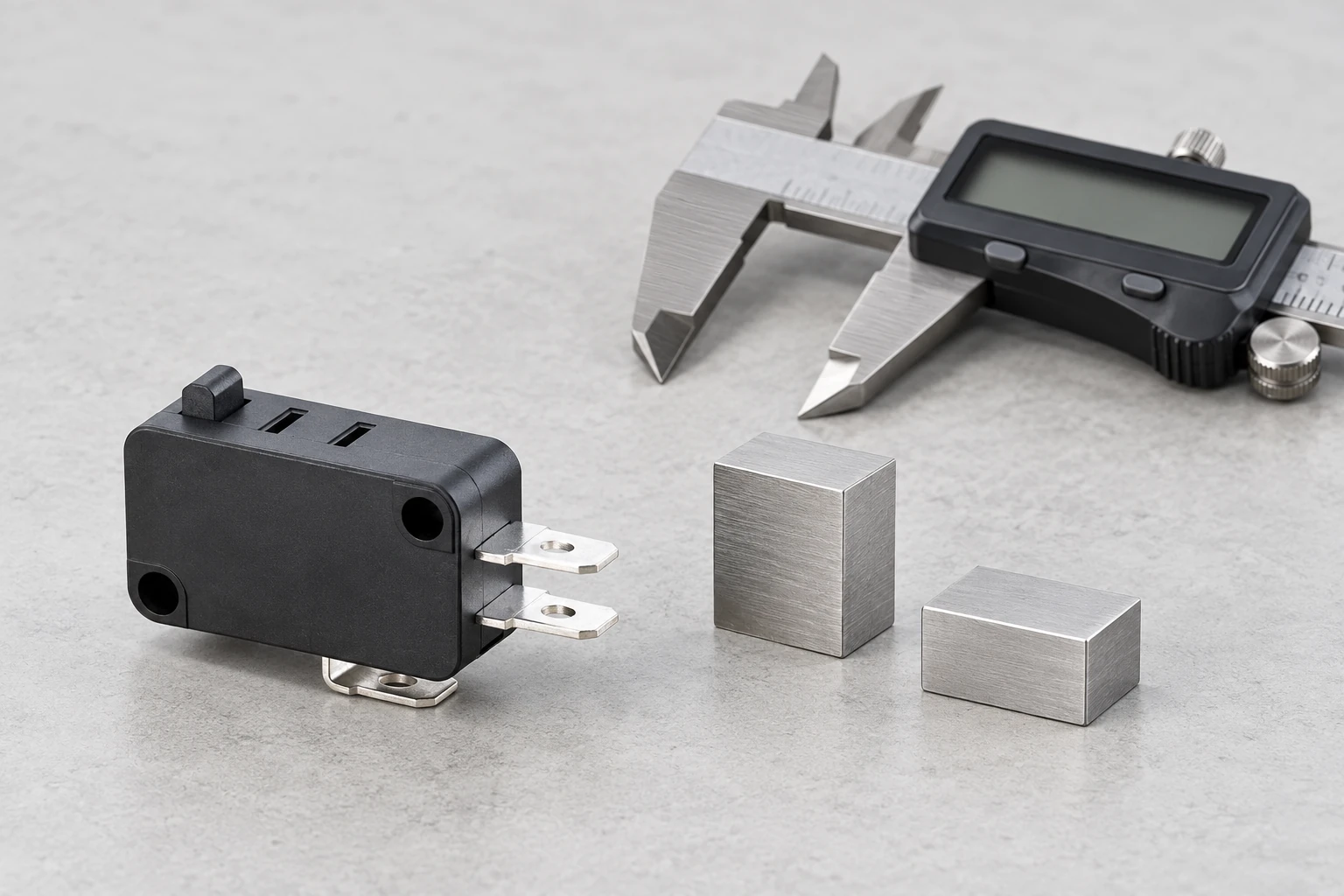
Draw one dimensional chain from a common reference
Choose a reference that connects the switch mount and the target position in the assembly. Define a positive direction and label the contribution of each relevant dimension. Include mounting location, bracket position, target location and any other features that establish relative motion. The chain should describe a physical relationship, not simply collect every tolerance appearing on the drawing. A dimension that does not affect the selected relationship belongs outside that particular calculation.
Avoid counting the same variation twice. If one drawing dimension is derived from two others, decide which independent dimensions define the chain. Pay attention to drawings that use different references or control location through a geometric requirement rather than a simple linear dimension. The engineering team may need an appropriate geometric analysis instead of a one-dimensional sum. State the simplifications and where they apply; a spreadsheet containing many numbers is not evidence that the underlying reference relationship is correct.
Calculate a simple interval before considering statistics
For a chain expressed as y = a + b – c, let each input have a lower and upper bound in millimetres. The conservative lower result is y_min = a_min + b_min – c_max, and the upper result is y_max = a_max + b_max – c_min. This interval calculation uses the combinations that reduce or increase the result. It does not require assuming a probability distribution or assuming that manufacturing variations are independent.
As a fictional arithmetic example, let a range from 10.0 to 10.2 mm, b from 2.0 to 2.1 mm, and c from 8.9 to 9.1 mm. The resulting y interval is 2.9 to 3.4 mm. These numbers are invented solely to explain the arithmetic; they are not KW7 dimensions, allowable travel or an approved fixture setting. A real design must replace every input with supported drawing or measured-process evidence and define what physical relationship y represents.
Compare the assembly interval with supported boundaries
If the actual imposed travel x must satisfy an approved minimum L and maximum U, a conservative interval check asks whether x_min is at least L and x_max is at most U. That comparison is valid only when x, L and U refer to the same mechanical reference, actuator point, direction and conditions. A contact event position measured from one surface cannot be compared directly with a drawing dimension referenced from another surface without the necessary conversion.
Return deserves a separate check. Define the withdrawn target position and the supported condition that allows the mechanism to reset. A design can satisfy the approach requirement yet retain contact or preload on the return path. Include relevant clearances, stops and interference risks. The operating force guide provides the separate force-selection context: a dimensional window alone does not prove that the available driving and return forces are adequate under the intended conditions.
Keep an evidence table beside the calculation
| Entrada | Evidência | Pergunta de revisão |
|---|---|---|
| Component boundary | Exact variant drawing and supported conditions | Same reference direction and contact point? |
| Assembly chain | Controlled dimensions and geometric requirements | Independent inputs without double counting? |
| Movement effect | Supported load and environmental cases | Does deflection change relative position? |
| Adjustment | Released setting and locking method | Can setting reach and retain the window? |
| Measurement | Method results and uncertainty | Does evidence support the claimed margin? |
| Production variation | Actual process evidence where required | Are statistical assumptions justified? |
The table is a review structure, not a list of universal acceptance values. Each number should point to its actual source, revision and applicability. Include units and signs explicitly. Record whether a limit is a manufacturing tolerance, an adjustment range, an observed measurement or a component requirement. Mixing those meanings can turn an adjustable nominal setting into an unjustified guarantee that every production assembly will remain within the same interval.
O NIST uncertainty guidance is relevant when measured values enter the review. Measurement uncertainty is different from the drawing tolerance assigned to an acceptable manufactured part. A measured prototype close to a boundary does not settle the production tolerance question. Preserve both the requirement and the evidence supporting the measurement, with a decision rule appropriate to the use. Do not quietly subtract uncertainty from a tolerance merely to create apparent design margin.
Include movement that dimensions alone do not describe
Bracket deflection, target compliance, wear, thermal changes and joint movement can change the relative position during use. Identify the mechanisms that matter to the actual assembly rather than adding generic allowances without evidence. A static dimensional chain may need a load-dependent contribution or separate condition cases. The mounting torque discussion concerns a related boundary: fastener tightening can affect location or housing condition, but a torque value alone does not establish assembly stiffness.
For a lever actuator, changing the target contact point can change the relationship between target movement and switch movement. Use the actual geometry and supported method. The lever-length selection guide addresses the separate actuator choice. A roller contacting a cam adds a changing surface relationship that may require geometric analysis over the path, not a single vertical distance at the end of travel. Document when a simple linear approximation is adequate and when it is not.
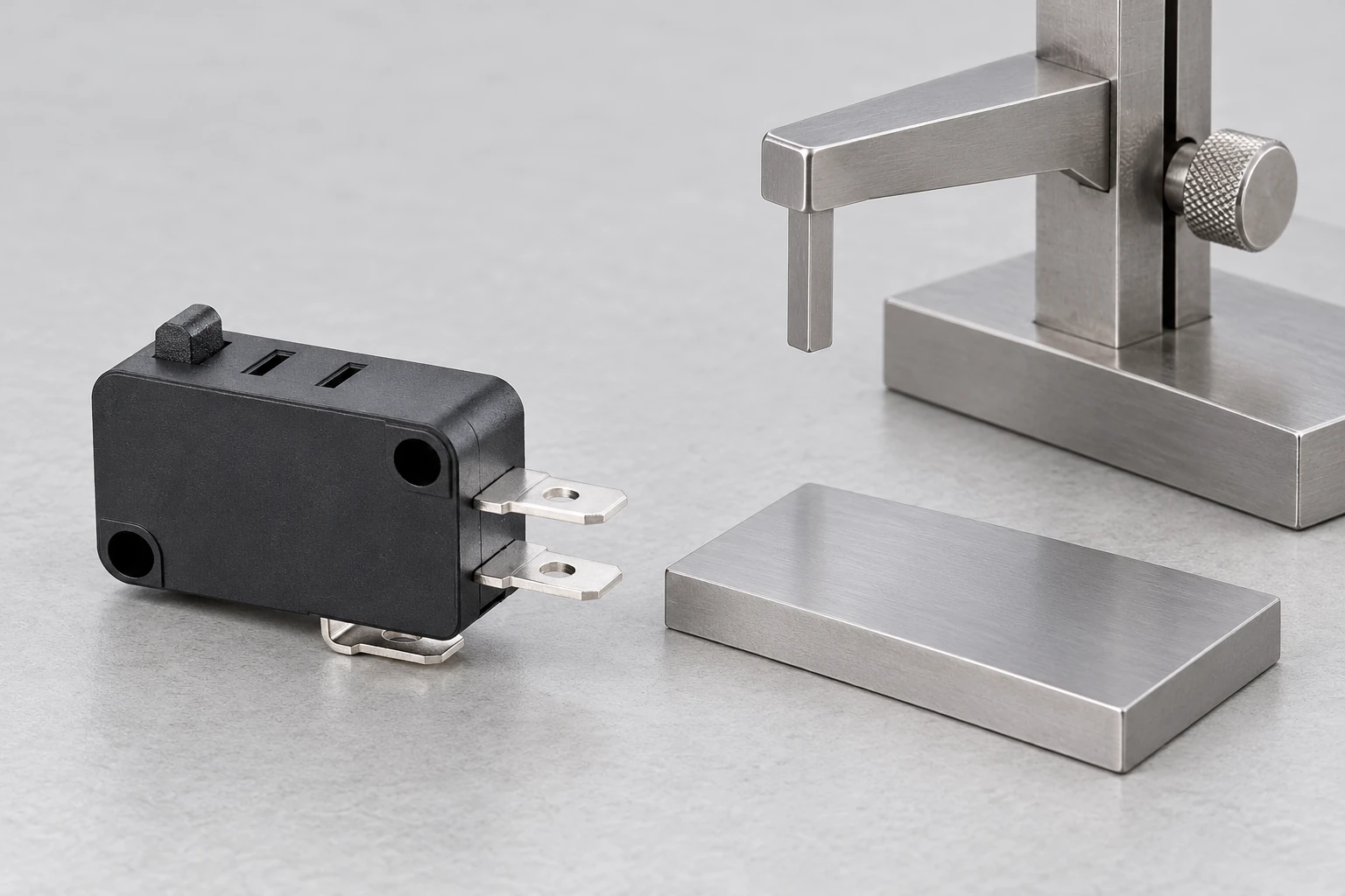
Treat adjustment as a controlled process
An adjustment slot can help set the assembly, but it also introduces process questions. Define the setting reference, tool, verification and locking method. State which dimensional variation the adjustment compensates for and which variation remains afterward. A technician finding a working position on one prototype is not the same as a released method that reliably establishes the required margin on every assembly. Consider whether tightening or subsequent service can move the adjusted position.
Check that the allowed adjustment range can reach the required setting across the relevant input variation. Then check the post-adjustment state, including the uncertainty or variation in the setting method. Keep adjustment authority clear: changing a machine stop may affect functions beyond the switch. Preserve the approved relationship between target position, component travel and the wider mechanism. Do not solve a local contact problem by moving a reference that another part of the machine relies on without the necessary review.
Use statistical assumptions only when supported
A statistical stack-up can be useful when the design and process evidence justify its assumptions. It should not be used automatically to make an inconvenient worst-case result smaller. Examine the distributions, process control, correlations and consequences of an out-of-window result. Dimensions created by the same operation may share variation. An assumption of independence can therefore be inappropriate even when each drawing lists its own tolerance. Record why the selected method fits the decision.
O NIST Engineering Statistics Handbook offers background on process characterization and statistical analysis. It does not supply a ready-made distribution for the OEM’s bracket, target or assembly operation. Use actual process evidence where a statistical model depends on it, and retain a path for reviewing that evidence after a supplier or process change. A successful prototype trial and a statistical estimate answer different questions and should remain separately identifiable in the design record.
Validate the model against representative assemblies
Measure the relevant references and observe operation and return on assemblies chosen to challenge the model. Record the component identity, assembly configuration, method and actual results. Look for effects the chain omitted, including motion out of the assumed plane, target flexibility or a reference that shifts under load. A disagreement is information about the model or measurement process; investigate it before adding a correction factor that merely makes the calculation match one sample.
Where deliberate boundary builds are practical and appropriate, define them through an approved plan. Do not damage components or impose unsupported travel to demonstrate a point. Separate a controlled engineering evaluation from production acceptance. After a change, identify whether it affects the dimensional chain, component boundaries, adjustment method or process distribution. Retain the calculation version linked to the released assembly so later investigations can understand which assumptions and source documents supported the decision.
Further learning: deformation under load
Khan Academy India – English: Stress & strain | Class 11 (India) | Physics | Khan Academy. Khan Academy explains stress and strain as background for load-dependent deformation. It does not provide KW7 force, travel or assembly-tolerance limits.
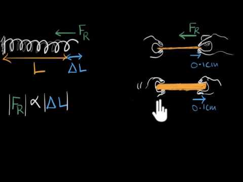
Watch Stress & strain | Class 11 (India) | Physics | Khan Academy.
This educational explanation provides background for understanding why a bracket or target can deform under force. It does not establish KW7 compliance, an allowable actuator force or a numerical assembly margin. The tolerance analysis needs actual geometry, materials, loads and supported component limits. Use the video to explain the physical question to the review team, then rely on the controlled design and validation evidence for the final decision.
Perguntas frequentes
Is nominal alignment enough?
No. Check the relevant permitted dimensional combinations and operating conditions. A center-of-tolerance prototype can work while another permitted assembly fails to operate or imposes unsupported movement.
Can I use dimensions from a product photograph?
No. Obtain the exact controlled drawing and supported actuator limits. A photograph cannot establish travel boundaries, tolerances or the reference conversions needed for an assembly calculation.
Does an adjustment slot remove the stack-up?
It may compensate for defined variation, but the setting range, method, locking and residual variation still require review. Verify both the ability to reach the setting and the final operating and return margins.
May I always replace worst-case sums with statistics?
No. Statistical methods need supported distributions, correlations and process evidence appropriate to the decision. Do not use an independence assumption merely to reduce an inconvenient calculated interval.