
Plunger limit switch side loading occurs when the target or surrounding mechanism applies a transverse load instead of the intended motion along the actuator’s permitted direction. It can arise from an angled approach, misalignment, a rubbing target, bracket movement or an inadequately guided part. Diagnose the complete interface before replacing the switch. A larger-looking housing or a deeper actuation setting does not automatically make an unsuitable approach acceptable.
O LEMA HL compact limit-switch family supplies the bare-plunger reference used in the figures. The loose guide and target specimens are explanatory objects, not an approved fixture. This guide provides no universal side-force allowance, approach angle or travel limit; use the exact model drawing and manufacturer guidance.
Identify the intended direction of actuation
Start with the controlled actuator drawing. Identify the motion direction, contact surface, reference point and allowed working travel. Do not infer those details from a catalogue photograph alone. A plain plunger and a roller or lever actuator can require different target arrangements.
O plunger selection guide addresses the wider selection context. This article focuses on identifying and removing unintended transverse loading in the machine-side interface.
Record the installed orientation and the complete target path. A target can approach correctly at one position but move sideways relative to the plunger as the mechanism rotates, flexes or reverses. Review the movement that actually occurs rather than only the nominal centerline on a sketch.
Separate side loading from excessive travel
Side loading concerns force direction and contact geometry. Excessive travel concerns how far the actuator is driven. Both can occur together, but they are not the same problem and a correction for one may leave the other unresolved.
Measure the relevant positions from defined references and compare them with the exact specification. Do not estimate a small displacement from a photograph without a reliable datum. The NIST SI length guidance supports consistent units and clear dimensional records.
If a target continues moving after the switch has operated, establish how that additional motion is accommodated. The switch should not become an unintended structural stop. Provide the separate machine stop or controlled movement required by the design and confirm its relationship to the sensing event.
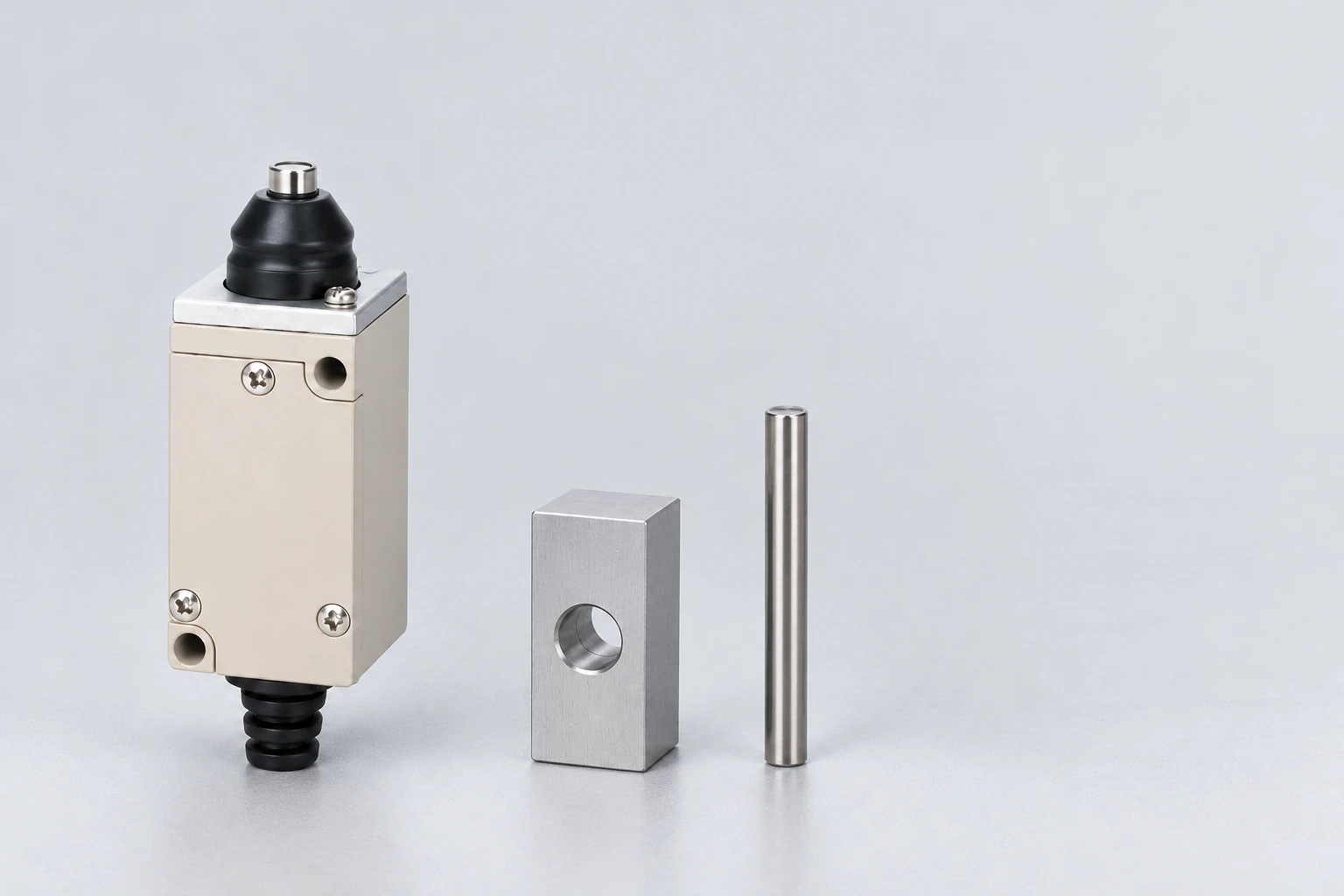
Inspect the contact surface and approach geometry
Look for an angled face, a sharp edge, a burr or a target that scrapes across the plunger. Record where contact begins and how the contact point moves during actuation. Surface condition and alignment matter alongside the nominal target shape.
Do not assume that a polished target is acceptable in every direction. The profile must still apply movement within the manufacturer’s supported arrangement. Conversely, an appropriate drawing can be defeated by a damaged or poorly finished production part.
O cam-profile guide covers approach, dwell and exit for a different actuator-interface question. Its roller illustrations do not approve an identical profile for a bare plunger. Select the target geometry for the actual actuator.
Check target guidance and support
Identify what keeps the moving target on its intended path. Review guide clearances, pivots, bearings, flexible members and the effects of load. An unconstrained part can shift sideways when it first touches the plunger, transferring an unintended force into the actuator.
A separate guide may be necessary in some designs, but its selection and dimensions need engineering review. Do not use the switch plunger itself to guide or locate a moving machine member unless the manufacturer explicitly approves that function.
O OpenStax discussion of torque explains why an offset force can create a moment in a support. Use it as mechanical background, not as a source of a permissible load for the HL switch or an untested bracket.
Inspect both sides of the mounting interface
A stable target can still side-load a moving or tilted switch. Check the switch bracket, locating surfaces, fastener condition and the supporting structure. Record any movement relative to the original references before changing the adjustment.
O mounting and repeatability guide addresses those support questions. A bracket that shifts under operating load can change both the trigger position and the direction of contact.
Do not over-tighten mounting hardware as a substitute for understanding the joint. Use the specified assembly method and inspect the panel or bracket for distortion. The objective is a controlled interface, not simply an adjustment that feels rigid during a hand check.
Include reversal and unusual permitted movement
Review every motion that the equipment is allowed to make: normal approach, return, reversal, setup and approved recovery. A target may withdraw cleanly in one sequence but catch the actuator during another. Record those conditions in the interface review.
Include the relevant tolerance combinations and load conditions. A nominal alignment can change when a guide reaches its allowed clearance or a mechanism carries its normal load. Do not accept a single carefully centered prototype as evidence for every permitted assembly.
Where the design uses an adjustable target or switch position, define the accepted setting and how it is checked. An undocumented service adjustment can create a side-load problem later even if the original production setting was satisfactory.
| Boundary | Inspect | Registar |
|---|---|---|
| Abordagem | Actual contact direction and surface | Model drawing and complete relative path |
| Viagem | Required movement and maximum imposed position | Defined references and approved limits |
| Guidance | Target freedom to move transversely | Guide condition load and permitted clearance |
| Support | Switch and target mounting stability | References fasteners and deflection observations |
| Return | Unobstructed withdrawal and reset | Target actuator and electrical states separately |
Investigate a sticky or damaged plunger safely
Follow the equipment’s isolation and stored-energy procedure before inspecting the actuator. Preserve the original target position and visible condition. Do not force, twist or lubricate a sticky plunger merely to make it move again.
Establish whether the external mechanism is holding the actuator or whether the actuator fails to return when the target is safely clear. Keep that observation separate from the electrical contact state. A released target, a returned plunger and a reset controller input are three observations that can help locate the boundary.
O HSE electrical-testing guidance provides safety context for the electrical portion of an investigation. It does not authorize a live mechanical experiment or replace the machine’s energy-control arrangements.
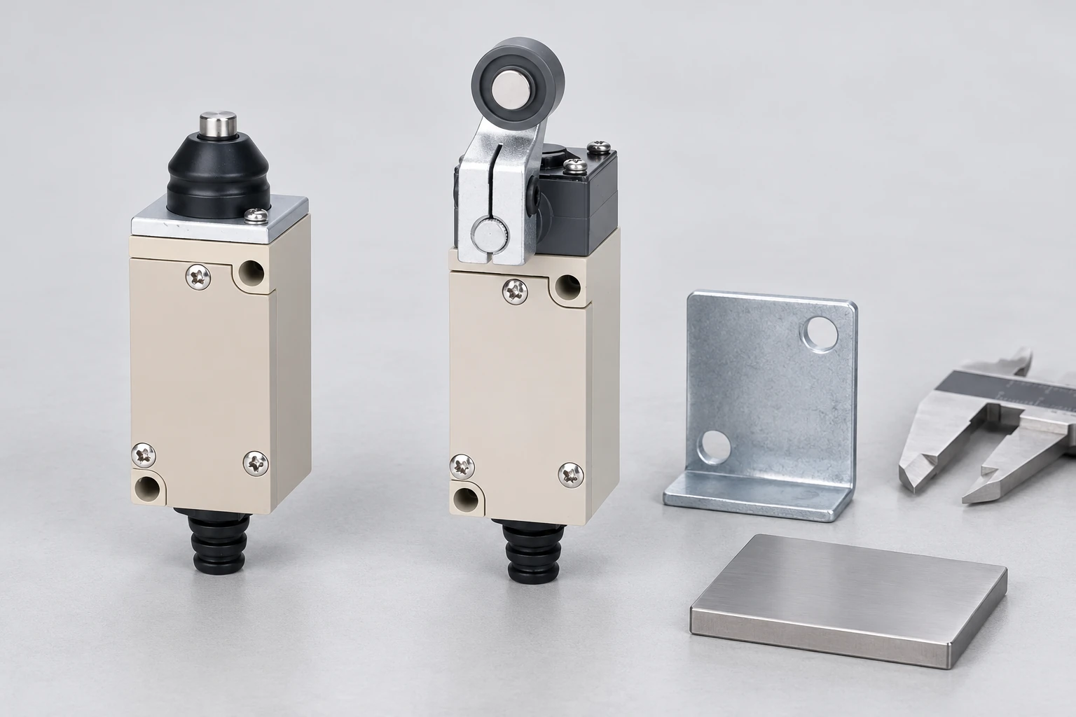
Correct the geometry before accepting a replacement
A replacement can temporarily restore operation while leaving the same target path or unstable support in place. Review the actual cause of the transverse load and revise the appropriate feature. That may concern the target, guidance, mounting or actuator selection, subject to the equipment design and supplier evidence.
Do not assume that changing to a roller or lever version is automatically interchangeable. The force, travel, mounting, approach and electrical characteristics still need review. Use the exact candidate drawing rather than choosing only from a similar external size.
For broader component substitution, consult the limit-switch replacement guide. Keep the corrected target-interface record with the replacement decision so the same mechanical problem is not transferred to a new part.
Keep measurement forces from changing the observation
A probe or measuring fixture can itself load a small actuator or flexible bracket. Record how the instrument is supported and whether taking the measurement changes the target position. Compare the unloaded reference with the observed operating condition through the agreed method. If the setup pushes the mechanism into alignment, the result may describe the fixture rather than the installed interface. Keep the support arrangement visible in photographs and record any constraints introduced during investigation.
Validate the completed interface
Define the intended contact path, working positions, release clearance and relevant speed or load conditions before testing. Observe the actual target and actuator movement through the complete sequence under an approved commissioning procedure.
Record whether the assembly remains aligned at the required extremes and whether the actuator returns freely. Verify the equipment input as a separate result. A contact that changes once does not prove that the mechanism avoids transverse loading throughout its service movement.
Send the full model, target sketch, mounting references, motion sequence and observed condition through the LEMA contact page. A useful inquiry asks whether the exact interface is supported and what evidence is needed, without inventing a universal side-load capacity.
Further learning: deformation under mechanical load
Khan Academy India – English: Stress & strain | Class 11 (India) | Physics | Khan Academy. Khan Academy explains stress and strain. It provides background for understanding deformation under mechanical load, not an HL side-force limit, actuator test method or approved target fixture.
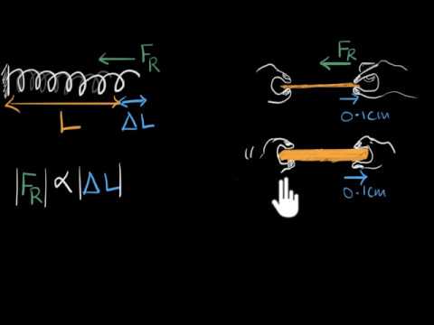
Watch Stress & strain | Class 11 (India) | Physics | Khan Academy.
Perguntas frequentes
How much side load can every plunger switch accept?
No universal allowance is established here. Use the exact model specification and manufacturer guidance for the supported approach and loads. An external photograph or housing size cannot establish a permissible transverse force.
Is side loading the same as overtravel?
No. Side loading concerns force direction and contact geometry; overtravel concerns displacement beyond the operating region. They can occur together, so check each boundary rather than assuming one adjustment corrects both.
Can the plunger guide the moving target?
Do not assume that structural function. Provide the target guidance required by the machine design and use the actuator within its supported conditions. Any approved locating or load-bearing function needs specific manufacturer evidence.
Will a new switch correct a misaligned target?
Not by itself. Establish the target path, guidance and mounting condition, then validate the corrected interface. A replacement can temporarily restore operation while the same transverse loading continues and causes another problem.