
An industrial limit switch replacement must preserve the original contact function, actuator relationship, mounting geometry and electrical duty, then pass the machine’s specified acceptance checks. Matching the housing or screw holes alone does not prove that the new part operates at the same machine position. Record the installation before removal and compare the original and candidate order codes against current drawings. This guide covers mechanical equipment position switches, not furnace temperature-limit devices. It explains how to protect an established setup during an approved repair; it does not guarantee unchanged timing or authorise substituting a generic switch into a safety-related function.
Confirm the fault and the approved service scope
Establish why a replacement is needed before ordering it. A loose bracket, worn target, cable defect or receiving-input problem can resemble a failed switch. Replacing a sound component can leave that problem unresolved and introduce a new operating-point difference. Use the position-switch troubleshooting guide to organise fault evidence before moving the installation.
For the broader position-detection context, see the limit switch application guide. Read the equipment service instructions and approved parts information. Identify whether the repair requires an exact service part, an approved alternative or a formal design review. A component used for ordinary position indication may have different verification requirements from one participating in a protective function. Do not assume an alternate model is acceptable because a supplier describes it as suitable for industrial machinery.
Secure the machine using its authorised isolation process, including stored mechanical, pneumatic or hydraulic energy where relevant. OSHA’s hazardous-energy control standard is a United States workplace reference for that process within its scope. A limit-switch signal, stop command or controller mode is not a substitute for the required energy isolation. Work that requires energised testing needs its own approved procedure.
Record the original position before loosening hardware
Photograph the installed switch, bracket, target and cable route from enough directions to show their relationship. Record the complete component identification and any orientation or locating feature. Include the machine position at which the switch is expected to operate and release, using the equipment’s approved reference method. A paint mark or photograph can help preserve a setup, but neither measures switching performance by itself.
Capture the target approach and the available travel after contact. Note the permitted approach direction, contact surface and how the actuator returns. A flexible whisker, roller lever and plunger do not impose the same geometry on a replacement. Document the exact construction rather than describing every actuator as a lever. Keep the removed component and its original location identified if further fault investigation is needed.
Record any existing adjustment settings and evidence of movement or wear. Avoid treating a visibly shifted bracket as the correct reference position simply because it is where the old switch was found. Where the documented setup and actual position disagree, refer the difference for assessment before copying it. The aim is to preserve an approved working relationship, not to reproduce an uninvestigated fault.
Compare original and candidate as complete assemblies
Collect the full order code, including suffixes, and obtain the relevant current drawings and product information for both parts. Compare mounting, actuator construction, operating and release conditions, contact arrangement, terminals and electrical duty. If the original information is unavailable, identify the missing evidence explicitly. A measured housing size is not enough to reconstruct the original specification.
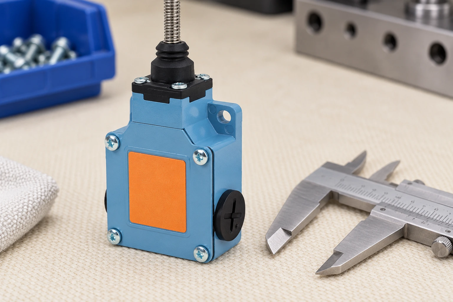
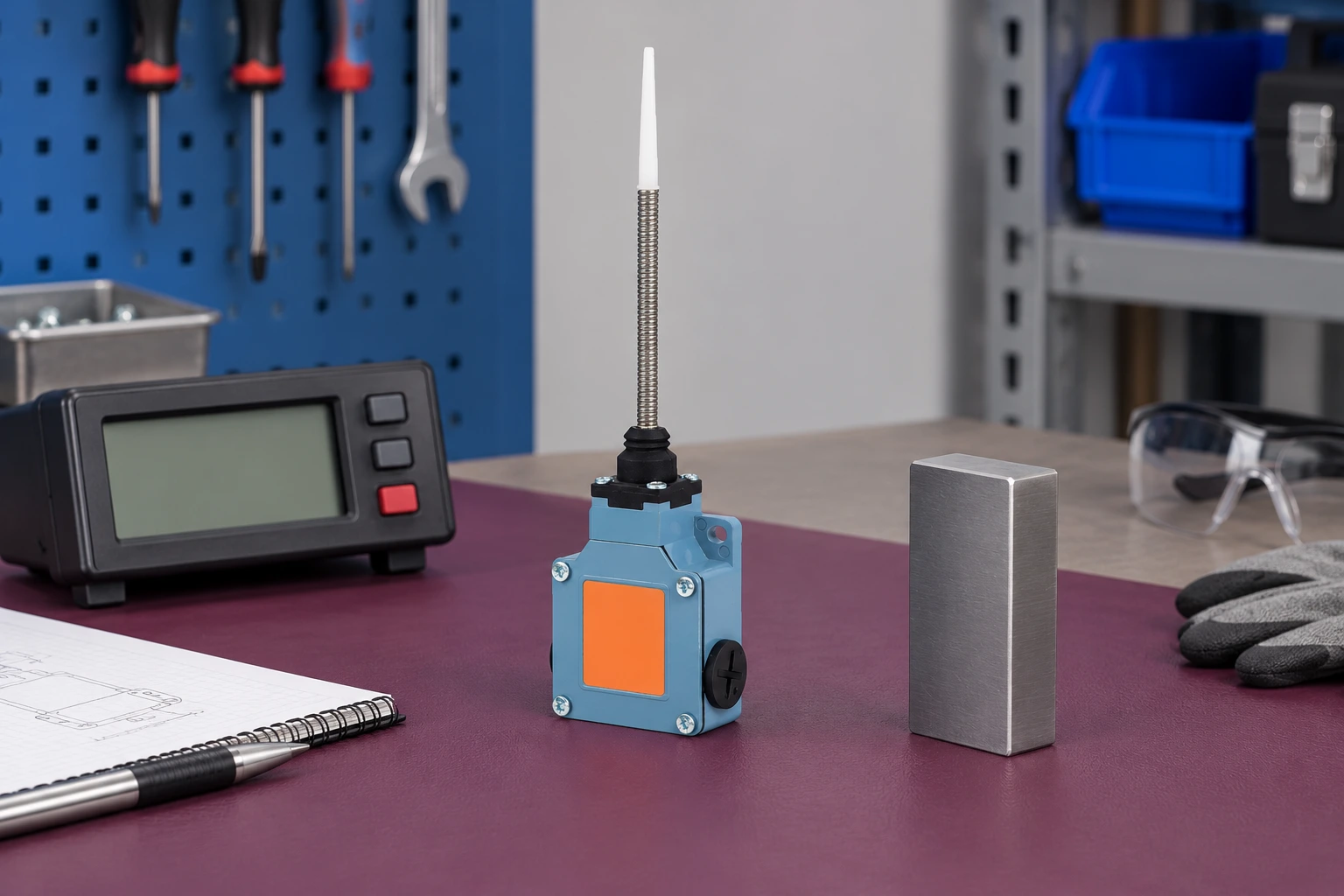
O LEMA LZ1 mechanical limit switch family is the real product reference illustrated in this guide. The images show its external enclosure and spring actuator form. They do not prove interchangeability with a removed machine component or supply an operating-point tolerance. Request information for the actual candidate order code rather than transferring a family description to every variant.
Confirm the expected electrical state using the equipment drawing and exact terminal diagram. A replacement that offers the same number of contacts can still have a different arrangement or operating action. Document the required released and operated states before reconnection. Do not infer terminal function from their physical position or copy the wiring of a different photographed model.
Replacement comparison and acceptance record
Use the qualitative checklist below to separate fit, function and verification. Each row needs evidence appropriate to the equipment and exact component. Unknown values should remain open items. Do not fill a missing operating range, torque or load rating with an estimate to make the comparison appear complete.
| Review area | Evidence to compare | Acceptance question |
|---|---|---|
| Component identity | Full original and candidate order codes and drawings | Is substitution permitted by the equipment owner? |
| Contact function | Exact terminal diagram and released/operated states | Does the original circuit function remain correct? |
| Actuator relationship | Approach, operation, release and permitted travel | Does the target stay within the approved operating range? |
| Mounting and cable | Support geometry, locating features and retention | Is the installation mechanically stable and serviceable? |
| Dever elétrico | Actual circuit and model-specific applicable ratings | Does the candidate suit the existing load and input? |
| Final machine sequence | Approved baseline and validation record | Are position, response and any protective function accepted? |
This is a qualitative engineering review checklist, not a product rating or certification table.
Check actuator travel and mounting before reconnection
Compare the installation geometry with the selected model’s permitted operation. The target should approach the intended surface, create the required operating travel and remain within the allowed mechanical range. Do not use the switch as the machine’s physical stop unless that specific use is approved. An actuator forced past its limit can fail even when its housing is a perfect physical fit.
Review the bracket and panel support, hole pattern, locating features and fastener requirements. Use the specified installation method rather than applying a universal tightening value. A bracket modification can alter the target relationship and should be reviewed as a change to the installation. The mounting and repeatability guide supplies a complementary framework for those decisions.
Inspect cable entries and supports at the same time. The lead should not pull the switch or load its termination when the machine moves within the permitted range. Restore approved covers and entry hardware without assuming that old fittings match the new enclosure. Check access for future service so that a physically fitting part does not leave an unsafe or unmaintainable installation.
Verify contact duty and the receiving interface
Compare the actual circuit with the candidate’s applicable electrical information. Record the voltage, AC or DC supply, load type and the role of the contacts. Switching a controller input and switching a connected load are different duties. An AC rating cannot be carried across to a DC application by changing the label, and a generic current value does not establish every load condition.
O AC and DC contact-rating guide explains that separate selection problem. For the repair, confirm that the candidate satisfies the existing circuit instead of silently changing the load or protection to suit an available part. If the interface requires a design change, document and approve it through the equipment’s authorised process before treating the replacement as equivalent.
Use an approved isolated check to confirm the specified contact states where appropriate. Parallel paths or connected electronics can make a continuity observation misleading. Follow the instrument and equipment instructions and never use a resistance range on an energised circuit. A correct isolated state is useful evidence, but it does not prove that the controller recognises the signal or that the complete machine responds as required.
Validate position and sequence as separate outcomes
After the approved assembly checks, follow the machine’s commissioning procedure under its defined conditions. Confirm the position at which the input is accepted, the release behavior and the intended response in each relevant travel direction. Keep the component observation, controller recognition and machine movement as separate entries in the test record. That separation makes an unexpected result easier to locate.
A new switch can alter an operating point within its permitted characteristics even when it is the same family and appears identical. The equipment’s acceptance criteria determine whether the final position and repeatability are acceptable. Do not claim unchanged timing from a successful hand-operated contact check. Compare the measured or observed outcomes with the approved baseline using the specified method.
O response-time and stopping-distance guide explains why sensing and stopping are not the same measurement. Drive response, controller processing and the final elements can contribute to the machine result. If the switch participates in a safety function, the complete protective system requires its specified validation; this article does not establish a safe stopping distance or approve a safety-device substitution.
Return the equipment to service with a traceable record
Record the removed and installed order codes, the reason for replacement, any approved adjustment and the acceptance results. Identify who performed the checks and who authorised return to service. Restore guards, labels, covers and cable supports according to the equipment procedure. Passing one cycle after the repair is not the same as completing the required validation across the permitted operating conditions.
O HSE work-equipment maintenance guidance provides a useful reference for planning maintenance safely and using suitable competence and procedures. Translate that principle into a defined repair scope and documented checks for the actual machine. Keep unresolved differences visible and assigned rather than recording a general statement that the replacement works.
For an OEM or supplier enquiry, provide the original identification, candidate requirements, mounting drawing, target relationship and circuit duty. Ask for missing evidence and state the acceptance process the equipment will require. Do not request or promise a universal drop-in substitute from a photograph. A well-controlled replacement ends with an approved comparison and verified machine behavior, with any change understood before normal production resumes.
Further learning
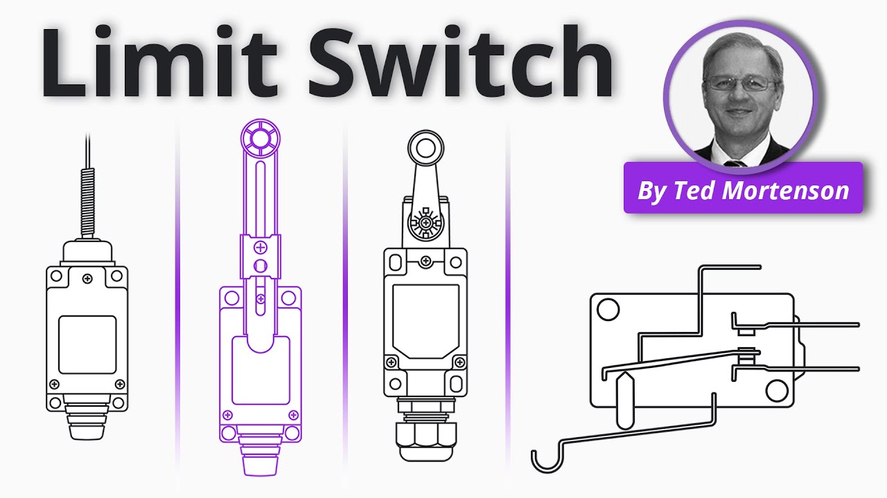
RealPars explains how actuator movement creates a contact change. Use the video to understand what a replacement must preserve; it is not an approval for a particular component or a machine safety-validation procedure.
Watch Limit Switch Explained | Working Principles
Perguntas frequentes
Can I choose a replacement by matching its mounting holes?
No. Also compare contact function, actuator characteristics, terminals, electrical duty and the equipment’s approval requirements. Physical fit alone cannot establish equivalent operation.
Will the same model always keep the same switching position?
Do not assume exact equality from the model name. Use the manufacturer’s applicable characteristics and the equipment’s specified position and repeatability acceptance checks after installation.
Can I bypass the switch while waiting for a replacement?
Do not bypass a protective function to continue operating the machine. Follow the authorised isolation, service and validation procedure for the particular equipment.
Does this procedure cover furnace limit switches?
No. It covers mechanical position switches on equipment. Furnace temperature-limit components perform a different function and require the appliance manufacturer’s approved service process.