
A 12V toggle switch decision starts with the panel circuit, not a voltage sticker. Define the switch function, DC load and inrush, cutout, terminals, and validation plan before requesting a model review. Similar levers can hide different contact forms and DC limits.
Important: A 12V label or an AC amp printed for another voltage class does not prove DC accessory suitability. Confirm voltage, current, load type, and inrush against the selected model documentation before release. Source note: IEC 61058-1 publication scope and selected-model documentation.
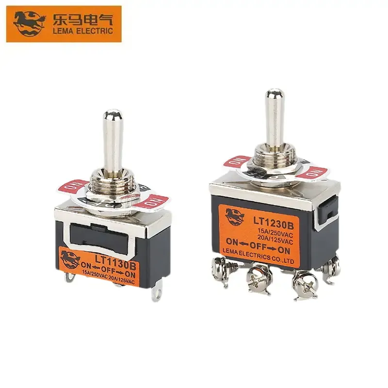
Part 1. What control job must the 12V toggle perform?
Write the operator action and the electrical result first. Note whether the switch must stay in position, return automatically, or select between two live paths. That description prevents buying a convenient lever that cannot express the required logic.
| Decision field | Input to document | Why it matters |
|---|---|---|
| Function | Maintained or momentary states | Controls circuit form |
| Load | Steady current and inrush at 12V DC | Frames contact review |
| Panel | Cutout, thickness, rear clearance | Controls mechanical fit |
| Harness | Terminal style and conductor size | Controls production wiring |
Public family options are indexed in the LEMA Toggle Switch product line; the drawing still owns the selection.
Part 2. How do ON-OFF, ON-OFF-ON, and momentary functions differ?
ON-OFF is a simple maintained path. ON-OFF-ON adds a center or alternate maintained path. Momentary positions spring back and suit test or jog duties.
Mixing these labels on a bill of materials creates panels that behave differently after a service swap.
Low-voltage sensing devices covered in the 12V micro switch overview answer a different job: position feedback, not panel operator control.
Part 3. How should DC load and inrush be documented?
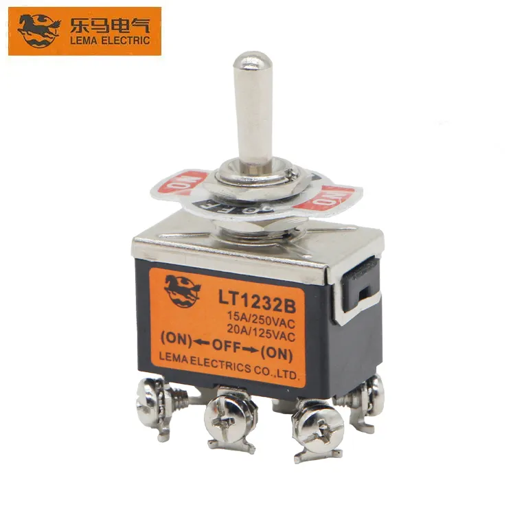
Record steady current, load type, and inrush at 12V DC. Lamp, motor, and solenoid loads can multiply the make current far above the running figure.
An AC amp printed for a different voltage class does not prove the same contact for DC accessory duty.
| Load note | What to capture | Risk if missed |
|---|---|---|
| Resistive | Steady current at 12V DC | Overstated margin |
| Inductive / motor | Inrush multiple and duration | Contact welding or early wear |
| Lamp / capacitive | Cold inrush | Contact bounce stress |
| Switching rate | Operations per hour or day | Heat accumulation |
Part 4. Which panel cutout and clearance inputs control fit?
Put hole diameter or rectangular cutout, panel thickness, locknut stack, lever swing, and rear clearance on one drawing. A switch that fits the hole can still foul a wiring duct or adjacent control when the lever is thrown.
- Confirm bushing thread and hole size from the model drawing.
- Check maximum panel thickness against the locknut and washer stack.
- Reserve clearance for the full lever travel and any boot or guard.
- Keep the rear envelope clear of harness bends and sharp edges.
Part 5. How should terminal style match the harness plan?
Screw terminals suit field service and large conductors. Quick-connect blades suit factory harnesses with controlled crimps.
Solder lugs need a process that limits heat into the switch body. Choose the harness method before samples freeze the BOM.
Part 6. How is a 12V panel switch validated before release?
Validate the production panel, harness, and load together. Cycle the switch at nominal and tolerance-extreme conditions, then confirm temperature rise and contact behavior under the documented inrush.
| Buyer should provide | Why it matters | Common mistake |
|---|---|---|
| Circuit form and safe state | Selects contact logic | Ordering by lever look alone |
| 12V DC load and inrush | Frames rating review | Copying an AC amp figure |
| Cutout and panel thickness | Confirms mechanical fit | Ignoring rear clearance |
| Terminal and conductor plan | Matches production wiring | Mixing screw and blade mid-run |
| Volume and sample timing | Sets quotation path | Requesting samples without a drawing |
Fit Boundary: this guide plans OEM panel selection for 12V toggle control. It does not certify a model rating, establish a safety function, or prove ingress or life results.
Part 7. How can LEMA support a 12V toggle inquiry?
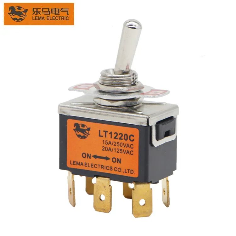
Use the LT1 series toggle switch page as a public starting point once the panel circuit and mounting envelope are written down. Sealed front-panel duties should move to a waterproof series review after the exposure envelope is defined.
Product recommendation: request a documented LEMA review against the panel drawing and DC load package. Do not approve a part from a generic “12V” label alone.
Send a toggle-switch RFQ with the drawing, duty, volume, and sample timing.
FAQs
Can any 12V-rated toggle switch run a motor accessory?
Not automatically. Motor inrush can far exceed the steady current, so the documented DC inductive or motor duty decides, not the 12V label alone.
What panel hole size do most 12V toggles use?
Many panel toggles use a round bushing near 12 mm / 15/32 in, but the selected model drawing is the authority for hole size, thread, and panel thickness.
Is ON-OFF the same as ON-OFF-ON for a 12V panel?
No. ON-OFF is a two-state maintained path; ON-OFF-ON adds another maintained path or center-off logic and changes the wiring and operator behavior.
Do AC amp ratings apply at 12V DC?
Not as a direct transfer. Confirm the DC voltage, current, and load type against the selected model documentation.
Which terminal style fits production harnesses?
Quick-connect blades suit controlled factory crimps; screw terminals suit serviceable field wiring. Match the style to the harness process before freezing samples.
What should a 12V toggle switch RFQ include?
Include circuit form, 12V DC load and inrush, cutout and panel thickness, terminal plan, environment, expected operations, volume, and sample timing.