
Set the trip point from the real conveyor mechanism, then document bracket adjustment, actuator path, tolerance stack, circuit input, and sample validation. This planning method does not promise anti-pinch, anti-jam, personnel protection, or conveyor performance. Use this article as an input checklist for an OEM discussion, not as a substitute for selected-model documentation or application testing.
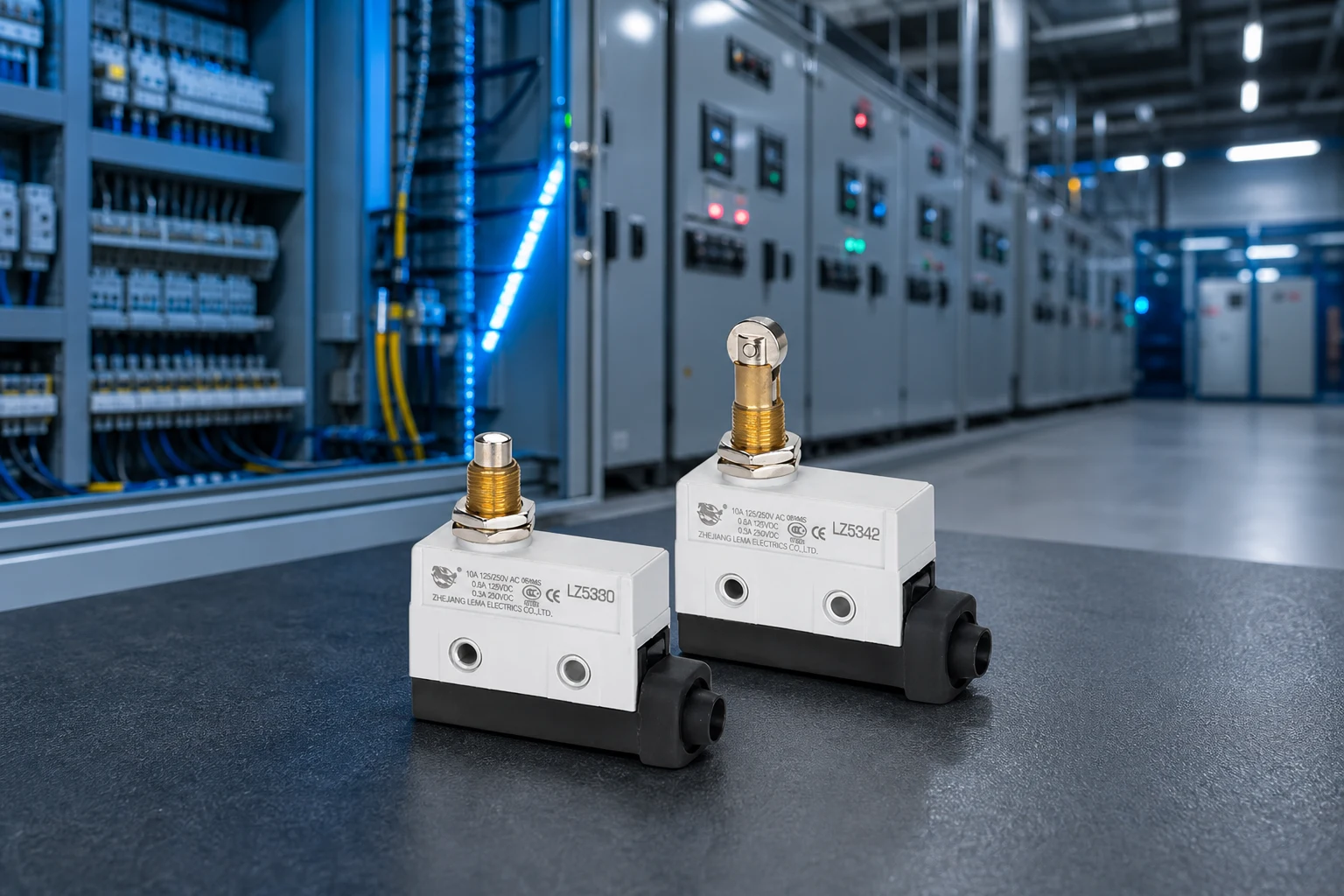
Part 1. What is adjustable travel setup?
Start with the actual mechanism and the decision that the switch must support. Define the required state change, reference position, approach direction, and operating conditions before choosing a general product family.
| Input group | What to record | Why it matters |
|---|---|---|
| Function | Required state and reference position | Connects the component to the installed task |
| Mechanism | Travel, force, and contact geometry | Defines actuator review |
| Circuit | Voltage, load type, current, and inrush | Defines electrical review |
| Environment | Exposure, service access, and mounting | Defines validation conditions |
Use the LEMA Micro Switch product line as a live category route, then confirm the selected option against its model documentation.
Part 2. Where should the trip position be measured?
Use fixed drawing references rather than descriptions such as “near the end.” Record the nominal condition, tolerances, reset condition, and changes that require the setting to be reviewed again.
For related mechanism choices, use the live mechanical actuator review article to frame the actuator and mounting discussion.
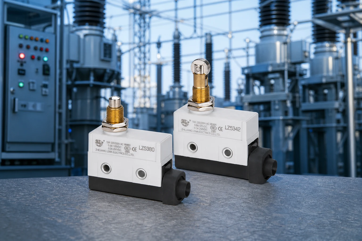
Part 3. How should the bracket adjustment be documented?
Describe the interface in enough detail that a sample can be installed in the production-intent arrangement. Include the contacting feature, movement direction, side-load risk, cable or terminal route, and accessibility for inspection.
Part 4. Which actuator-path checks matter?
Compare the mechanism’s travel envelope with the selected model drawing. A useful review checks free position, operating position, release, maximum travel, and clearances with neighboring parts.
| Validation check | Question to answer | Record |
|---|---|---|
| Actuation | Does the mechanism reach the intended state across tolerances? | Measured travel and position |
| Mounting | Is alignment controlled through assembly and service? | Bracket and fastener references |
| Circuit | Is the real duty documented? | Load and controller input |
| Environment | Does the sample match the installed exposure? | Test conditions and assembly state |
Part 5. How should the circuit input be reviewed?
Validate with the intended bracket, actuator, harness, and control input. Record which change to a mating part, wire route, mounting feature, or operating condition triggers a new review.
- Check free, operated, and release states.
- Inspect alignment, side load, and travel margin.
- Review the actual electrical duty against model documentation.
- Document the installed environment and test method.
Part 6. What belongs in the RFQ and Fit Boundary?
RFQ input checklist
- Function and required circuit state
- Mechanism drawing, actuator path, mounting, and tolerances
- Voltage, current, load type, inrush, and controller input
- Environment, validation target, volume, and sample timing
Fit Boundary
This guide helps define an application review. It does not certify an installation, establish a safety function, prove a rating, or guarantee a machine-level result.
Part 7. How can LEMA support a conveyor inquiry?
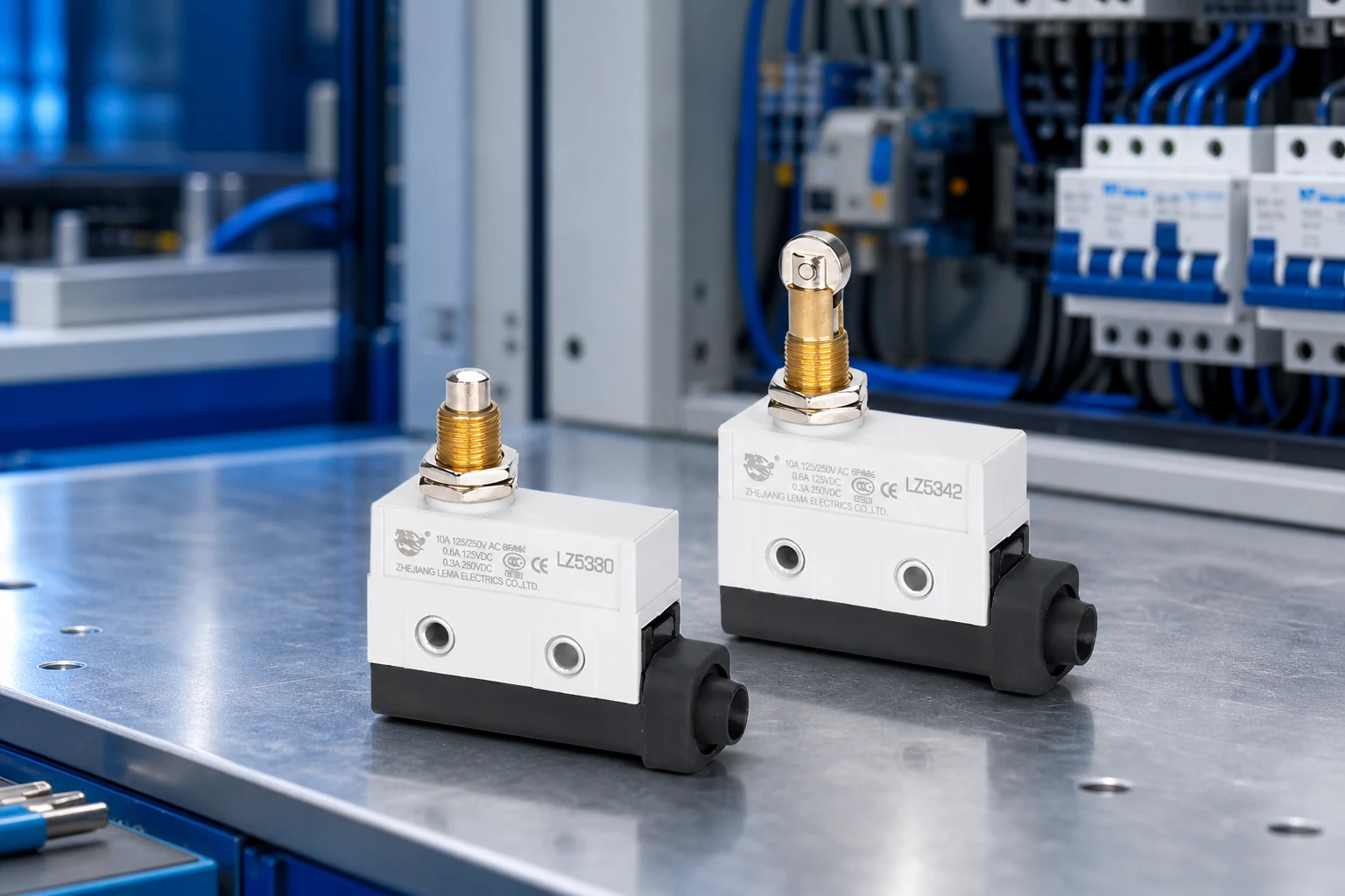
Use the LZ15 series micro switch page as a public starting point for an OEM inquiry. Supply the actual drawing, circuit duty, environment, and validation target for model-level discussion.
Product recommendation: ask for a review after the RFQ fields are complete. Do not select a part from a generic application label alone.
Send an OEM switch RFQ with the application package.
FAQs
What is an adjustable limit switch setup?
It is a documented way to position and review a switch actuation point in a specific mechanism; the final setting depends on the installed drawing and model information.
Where should conveyor trip position be measured?
Measure from defined machine reference points and record nominal position, tolerances, reset position, and adjustment range.
Does an adjustable switch prevent a conveyor jam?
No. A trip-point component is not a promise to detect every condition or to deliver a system performance outcome.
Why does bracket adjustment need a drawing?
The drawing controls reference surfaces, slot range, fastener position, actuator alignment, and the settings that must be rechecked after service.
What should be tested on a sample?
Review the production-intent mechanism, travel path, mounting, circuit input, and tolerance conditions against the selected model documentation.
What should a conveyor switch RFQ include?
Provide the conveyor drawing, reference positions, travel path, actuator type, circuit duty, environment, validation method, volume, and sample timing.