
An automotive micro switch is a compact snap-action component that reports a defined mechanical state inside a vehicle-adjacent module. The right choice comes from the module drawing and validation plan: actuator travel, contact load, mounting tolerance, vibration, sealing, wiring, and service access must agree before prototype approval. A generic “automotive” label or an IP code is not a substitute for that work.
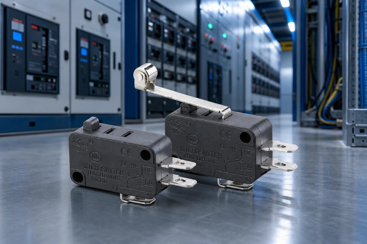
Part 1. What does an automotive micro switch do in a module?
A micro switch changes contact state at a defined actuator position. In a vehicle-adjacent assembly, that change can tell a controller that a latch, cover, lever, seat, pedal mechanism, charging flap, or service panel has reached an intended position. The component is a state input; the module controller and system design decide what should happen next.
Start with the function rather than the package size. Write the condition to detect, the safe state if the actuator is released, the action expected from the downstream circuit, and the consequence of a false signal. That separates a simple position report from a function that needs a redundant sensor, diagnostic path, or a different technology.
| Module question | What the switch must prove | Typical design owner |
|---|---|---|
| What moved? | Door, latch, lever, cover, or mechanical linkage reached its target position | Mechanical design |
| What state is safe? | NO, NC, or changeover contact behavior after actuator release | Electrical design |
| What happens next? | Controller input, warning, enable, or interlock response | Controls / software |
| How is it verified? | Travel, load, environment, and life checks in the module | Validation team |
Use the LEMA Micro Switch product line as the commercial starting point, then keep the selected series tied to a complete drawing and a quoted model document.
Part 2. Which vehicle-adjacent functions can use snap action?
Snap-action devices are useful where a repeatable mechanical change must become a discrete electrical signal. Common concepts include latch-position detection, access-panel confirmation, lever end position, auxiliary service covers, and protected enclosure mechanisms. The system may be inside a vehicle, attached to an accessory, or part of a vehicle-adjacent charging or equipment module.
Do not turn this list into a fit claim. Two assemblies can share the same function name but have completely different loads, temperatures, contamination routes, and validation requirements. A door-latch application with a short, rigid travel path is not the same as a vibrating external module with a flexible cable.
- Position reporting: a controller receives an open/closed or reached/not-reached state.
- Mechanism sequencing: a state signal permits the next motion only after a linkage completes its travel.
- Service access: the module recognizes an access cover or panel position.
- Auxiliary interlock: a mechanical state can be included in a broader system interlock, subject to the OEM safety analysis.
For modules exposed to splash or routing constraints, compare the separate sealed cable and harness selection method. Sealing at the switch enclosure does not remove the need to protect the connector, grommet, and cable path.
Part 3. How do actuator travel and tolerance stack-up affect reliability?
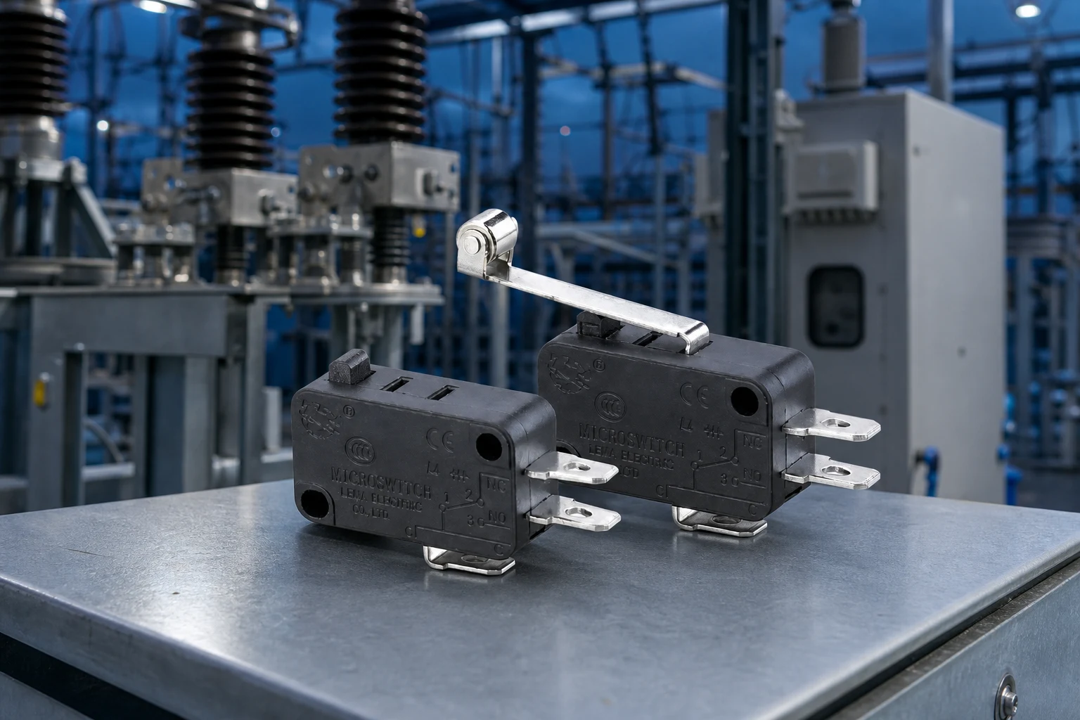
Most field-like failures begin at the mechanical interface. A switch may work on a nominal bench fixture yet operate too near its trip point after bracket variation, latch wear, thermal movement, or vibration. The mechanical drawing should define free position, operating point, release point, allowable overtravel, and the direction in which the actuator is loaded.
Build the tolerance stack from the moving part to the switch mounting face. Include bracket thickness, fastener clearance, molded-part shrink variation, lever geometry, and cable or connector restraint. Review worst-case high and low stacks, not only the CAD nominal.
| Mechanical item | Validation question | Failure if ignored |
|---|---|---|
| Operating travel | Does every build cross the operating point? | Intermittent state change |
| Overtravel | Is force limited after contact transfer? | Actuator or switch damage |
| Release margin | Does the signal reset after real-world movement? | Latched or chattering input |
| Mounting datum | Is the switch located from controlled surfaces? | Unit-to-unit variation |
| Actuator direction | Is the lever loaded as the supplier specifies? | Unexpected wear or force change |
When a roller or lever interface is needed, use the site’s roller actuator selection guide to organize the actuator discussion. Confirm the actual operating force and geometry on the quotation, not from a related article.
Part 4. What environmental checks belong in the module plan?
Environmental selection begins with the installed location. Ask whether the switch sees cabin conditions, a humid compartment, splash, dust, cleaning chemicals, road contamination, thermal cycling, or cable motion. The question is not simply “Do we need waterproof?” It is which exposure reaches the switch body, terminals, and harness over the module life.
An IP designation describes a defined ingress-test context. It does not by itself establish temperature endurance, vibration resistance, connector retention, corrosion resistance, or program qualification. Treat every label as one input to the module validation plan.
- Map water, dust, and chemical paths into the enclosure.
- Record the installed orientation and any drain or vent route.
- Test with the production bracket, fasteners, connector, and strain relief.
- Inspect contact behavior before and after environmental conditioning.
The waterproof micro switch design context article is useful for general sealing language, while the final module plan must use the selected switch’s data and the OEM test procedure.
Part 5. How should teams define the electrical interface and harness?
Contact form, load type, terminals, and harness routing belong in the same specification. A controller input may require a different contact strategy from a load-switched circuit. Do not assume that a contact suitable for a low-current signal is suitable for a motor, relay coil, lamp, or other inductive load.
Define whether the circuit needs normally open, normally closed, or changeover behavior at the safe mechanical state. Then identify voltage, current, inrush, connector type, wire insulation, circuit protection, and expected service access. The harness drawing should also show how motion is isolated from the terminal or lead exit.
For a compact dry module, a public KW7 series micro switch route may be a useful inquiry starting point. A sealed version may suit a different exposure path, but neither selection should be made without the exact electrical and mechanical inputs.
Part 6. What should OEM teams validate before release?
Release testing should prove the module state across production variation, not merely show that a loose switch clicks. Use the exact bracket, actuator, wiring, and controller input where possible. Compare initial samples with conditioned samples and record the state seen by the final electronics.
RFQ and validation checklist
- Function to detect and required safe contact state
- Contact form, circuit voltage, current, load type, and inrush
- Motion profile, travel window, operating-force target, and overtravel limit
- Mounting drawing, tolerance stack, actuator direction, and fastener scheme
- Installed environment, exposure routes, cable/terminal layout, and service access
- Prototype test plan, required documents, annual volume, and timing
Fit Boundary
This approach suits teams that can supply those module inputs. It is not a replacement for a vehicle-program DVP, functional-safety analysis, or evidence that a generic micro switch is approved for an automotive application. If the function needs continuous position feedback, coded sensing, or redundant diagnostics, evaluate a sensing architecture designed for that requirement.
Part 7. How can LEMA support the inquiry path?
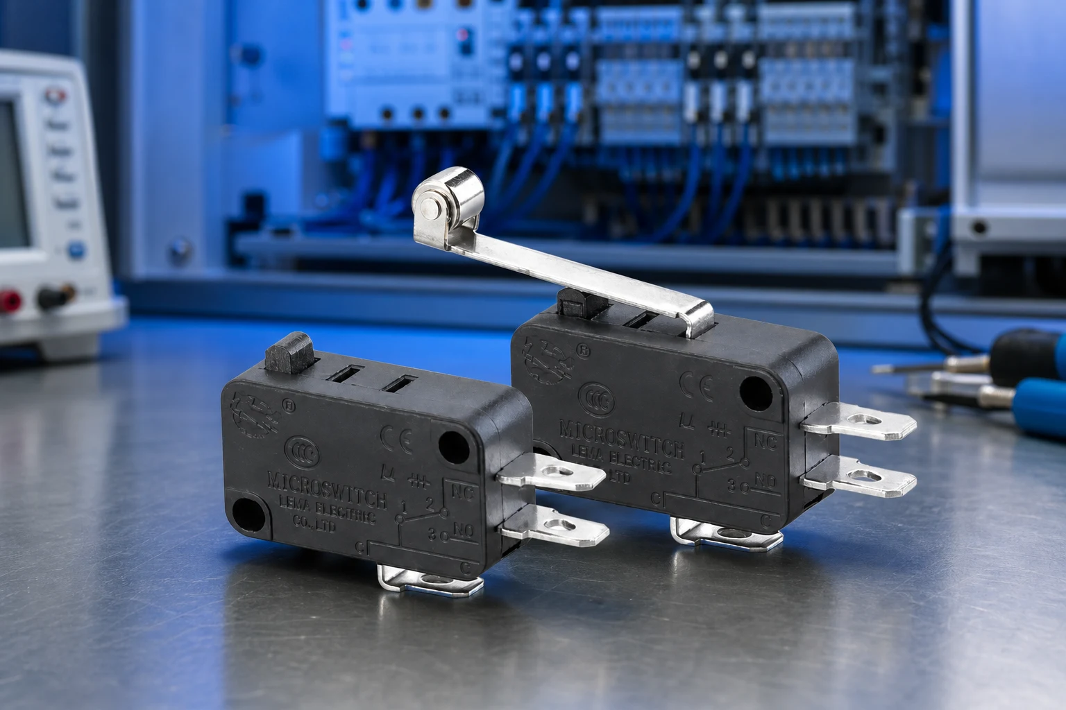
LEMA publishes micro-switch families for OEM inquiry. Begin with the KW7 series micro switch when a compact snap-action package matches the mechanical concept. When the module exposure calls for a waterproof-family review, use the KW7F waterproof micro switch series as an inquiry route.
Product recommendation: send the completed module input list to LEMA with a drawing and prototype test target. Do not select a series solely because an application is described as automotive. LEMA needs the actual load, travel, environment, and documentation requirement to confirm a quoted model boundary.
Browse the Micro Switch category or send an OEM module RFQ with your drawing package.
FAQs
What does an automotive micro switch do?
It converts a defined mechanical position into a discrete electrical contact state for a module or controller. The system design decides how that state is used.
Where are micro switches used in vehicle modules?
They can be considered for latch, cover, lever, service-panel, and auxiliary mechanism position detection where a snap-action contact fits the architecture.
How do vibration and tolerance affect a micro switch?
They can move the actuator near its operating or release point, causing false or intermittent signals. Validate worst-case travel and mounting variation in the assembled module.
Does an IP rating make a switch automotive-grade?
No. An IP code addresses a defined ingress-test context. It does not establish program-specific electrical, thermal, vibration, documentation, or validation requirements.
What information belongs in an automotive micro switch RFQ?
Provide the function, contact state, electrical load, motion and mounting drawing, environment, terminal or harness need, validation target, timing, and volume.
Can a general industrial micro switch be used in a vehicle module?
Only after the OEM confirms the selected model and module assembly meet the project’s engineering and validation requirements. A broad category label is not proof of fit.
When should an OEM use another sensing method?
Use another architecture when the function requires continuous position data, coded identification, redundancy, diagnostics, or conditions outside the selected switch’s documented limits.