
Limit switch cable gland selection requires matching the actual enclosure entry, cable jacket and assembly requirements. The entry thread and the cable sealing range are separate checks. A gland that screws into the housing can still fail to grip or seal the cable correctly. Confirm the controlled drawings and installation instructions before choosing an accessory.
El Interruptor de límite de la serie LZ1, cuerpo de aleación de aluminio duradero, clasificación IP66 is the LEMA product reference illustrated here. Its photograph identifies the external product, not an unlisted rating, accessory compatibility or test result. Obtain the current specification for the full order code before approving an assembly.
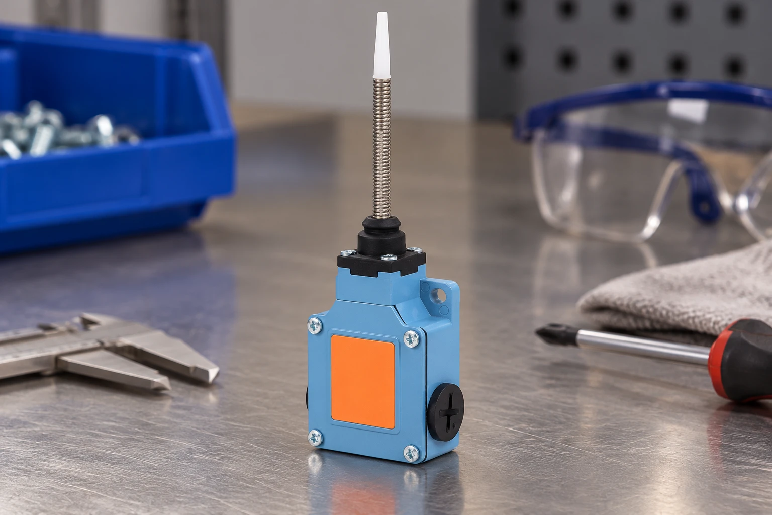
Identify the Enclosure Entry Before Selecting Hardware
Begin with the switch enclosure drawing and the supplier’s entry instructions. Establish whether the opening is threaded or intended for a through-mounted gland with a locknut. For a threaded opening, identify the thread form, pitch, engagement requirements, and the sealing arrangement specified for that interface. Similar-looking threads can start together yet fail to engage correctly or leave an unsuitable sealing condition.
Do not use assembly torque to compensate for a mismatched thread. Resistance during installation may indicate cross-threading, damaged coatings, debris, or incompatible geometry rather than a properly seated connection. Obtain an authoritative entry specification when the drawing is incomplete. Checking a loose sample alone can be misleading if production enclosures come from different tooling or finishing processes.
Examine the exterior and interior seating surfaces. A sealing washer needs a suitable contact face, while a locknut needs room to seat without colliding with internal parts. Thin walls, curved surfaces, recessed entries, casting texture, and nearby ribs can affect the arrangement. Confirm tool access with the switch mounted in its intended position, not only while it is loose on a bench.
Separate the Entry Seal from the Cable Seal
A cable entry commonly contains distinct leakage paths. Moisture may pass between the gland body and enclosure, or between the gland seal and cable jacket. Closing one path does not necessarily close the other. Review each interface separately and identify the feature intended to seal it, such as a specified washer, sealing ring, thread arrangement, or cable compression element.
Do not assume that thread engagement alone provides the enclosure seal. Some designs rely on a face seal, while others require a particular sealing method defined by the hardware supplier. Adding tape, compound, or an extra washer without approval can alter seating, material compatibility, or assembly behavior. It can also obscure the real cause of leakage during investigation.
Adapters create additional interfaces that need the same review. An adapter may solve a thread mismatch but introduce another sealing face, increase the projection from the housing, and change cable routing. Record the complete entry stack in the assembly documentation. Describing only the gland leaves production and maintenance personnel to improvise the remaining parts.
Distinguish Gland Sealing from Strain Retention
The gland seal closes around the jacket; strain retention resists cable movement that could disturb that seal or load the internal terminations. These functions may share parts, but they should not be treated as interchangeable. A cable can feel firmly gripped while the sealing interface remains unsuitable. Conversely, a seal may appear seated while the cable still transfers movement to a terminal.
Review how the selected gland develops retention and whether that mechanism is suitable for the jacket construction. A soft jacket may deform, while a hard or slippery jacket may behave differently under the same assembly method. Tightening beyond the specified procedure is not a reliable remedy. Excessive compression can damage the jacket, distort the sealing element, or stress the gland body.
Consider loads from installation, maintenance, vibration, and normal machine movement. Where the cable route imposes bending or repeated motion near the entry, evaluate external support independently of the gland. A clamp or routing feature may be needed to keep the entry from becoming the cable’s pivot point. Internal conductor slack should accommodate assembly without substituting for proper retention.
Select Against the Actual Cable Diameter and Jacket
Use the cable manufacturer’s dimensional information as a starting point, then inspect representative production cable. The relevant dimension is the outside jacket presented to the gland, not conductor size, insulation diameter, or a nominal designation on a purchasing description. Cable variants with similar electrical characteristics can have different jacket dimensions and constructions, changing how they fit an otherwise unchanged gland.
Account for manufacturing variation without assuming that every cable sold under a broad description is equivalent. Review the gland supplier’s declared cable compatibility and assembly instructions against the actual cable specification. When the fit is uncertain, request clarification or evaluate a different gland and seal combination. A cable that can be pushed through the opening is not necessarily suitable for sealing or retention.
Jacket condition matters as much as diameter. Raised markings, seams, abrasion, cuts, contamination, and local deformation may interrupt contact with the sealing element. Check the part of the jacket that will sit inside the gland after termination. Avoid positioning the seal over damaged material or over a region distorted by temporary clamps, packaging, or cable preparation.
Evaluate Jacket Shape and Material Compatibility
A circular seal should not be assumed to close reliably around every cable profile. Oval, flat, ribbed, bonded, or irregular jackets require an entry arrangement intended for that shape. Compressing a nonmatching cable harder can leave channels beside the jacket while damaging its surface. Select hardware with documented compatibility rather than relying on appearance after tightening.
Material compatibility includes the cable jacket, gland body, seal, enclosure, and any approved assembly aid. Consider the substances and conditions encountered during machine cleaning, operation, storage, and service. Swelling, hardening, softening, cracking, or relaxation may change both sealing and retention. An initial fit check cannot establish how an unsuitable material combination will behave after exposure.
Avoid passing separate cables through a seal intended for a single jacket unless the entry system is specifically designed for that arrangement. Spaces between adjacent jackets can remain open even when the outside group feels tightly compressed. Similarly, a sleeve or improvised wrap changes the sealing surface and should not be treated as a validated replacement for compatible entry hardware.
Use a Qualitative Selection Review
A qualitative review helps purchasing, design, and assembly teams compare candidates without reducing the decision to thread size or appearance. Record what is known, what remains conditional, and what evidence is needed. The following checks support selection but do not establish an ingress rating or replace the component suppliers’ instructions.
| Selection area | Suitable basis for review | Reason to stop and resolve |
|---|---|---|
| Enclosure entry | Documented thread or through-hole arrangement with usable seating surfaces | Uncertain thread identity, damaged entry, or obstructed seating |
| Entry seal | Specified sealing feature compatible with the enclosure interface | Reliance on improvised compounds or unexplained extra washers |
| Cable fit | Actual jacket dimensions and profile match the intended seal | Nominal cable description used without checking the jacket |
| Retention | Defined gripping method supported by representative assembly checks | Cable movement transferred directly to internal terminations |
| Unused openings | Compatible closure hardware with a defined installation method | Open entries or temporary shipping closures left in service |
| Assembly evidence | Recorded configuration, inspection, and relevant evaluation results | Performance inferred solely from an individual component description |
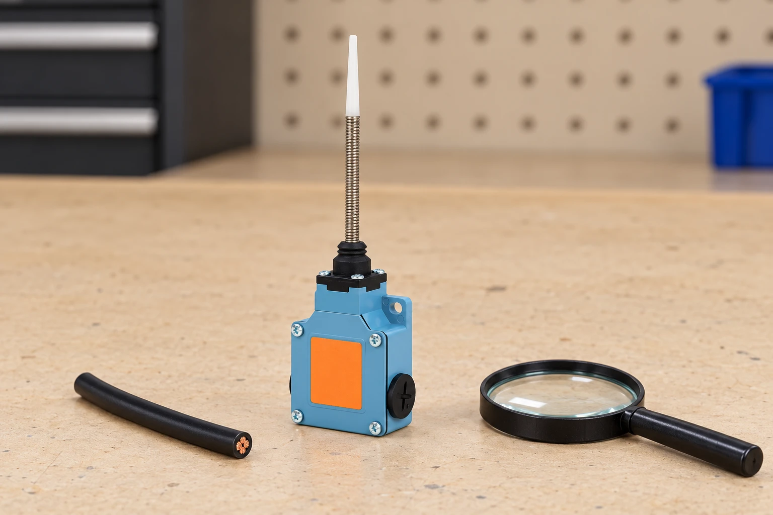
Close Unused Entries as Deliberately as Used Entries
An unused opening remains part of the enclosure boundary. Select a closure intended for that entry and application, with the appropriate thread or mounting arrangement and sealing features. Do not assume that a shipping cap, dust cover, or transport plug is suitable for service. Confirm its intended function from the applicable documentation.
Apply the same seating, compatibility, and access checks used for a gland. A closure can leak around its perimeter even though its center is solid. Keep unused-entry hardware on the bill of materials and assembly drawing so that omissions are visible. If a field option later uses that opening, define the approved replacement entry arrangement rather than leaving the choice entirely to the installer.
Control Installation and Assembly Sequence
Provide an assembly instruction that identifies the gland, seals, locknut where applicable, closure hardware, and cable. Show the orientation and order of parts, along with the supplier’s tightening method. Separate the operation that secures the body to the enclosure from the operation that compresses the cable seal. Otherwise, tightening a cap may unintentionally rotate or loosen the body.
Validate the complete cable-entry assembly
Evaluate the switch housing, gland, cable, seals, closures and routing as the configuration that will actually be supplied. Define the relevant ingress and retention assessments with qualified personnel and the applicable specification. Record the hardware order codes, jacket dimensions, installation method and observations. A short visual examination or hand pull is not a substitute for a specified ingress or mechanical test. Do not represent an accessory rating as a test result for the assembled switch.
After acceptance, preserve the bill of materials and assembly instructions, including unused-entry closures. A different cable jacket or seal can require another review even when its nominal electrical description is unchanged. In a technical inquiry, provide the entry drawing, complete cable specification, required environment and routing constraints so the supplier can identify unresolved interfaces before samples are approved.
Technical references and the scope of this review
IEC 62444 cable glands: IEC 62444 addresses cable-gland construction and performance. Its scope does not make any selected gland compatible with an unknown switch entry.
IEC 60529 enclosure protection: IEC 60529 concerns enclosure protection classification. Review the complete installed entry rather than treating a gland marking as proof of the finished assembly rating.
For the wider component decision, see ¿Para qué se utiliza un interruptor de límite? Aplicaciones industriales y guía de selección. Complementary checks are covered in Limit Switch Troubleshooting: No Signal, Chatter and Misalignment y Industrial Limit Switch Replacement: Preserve Position and Validate Timing. These pages address separate questions and do not replace the acceptance evidence defined here.
Further learning
This independent stress-and-strain lesson provides background for cable retention and material loading. It does not establish a gland seal or an ingress rating.
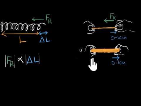
Watch Stress & strain | Class 11 (India) | Physics | Khan Academy — Khan Academy India – English
Preguntas frecuentes
Does matching the entry thread prove compatibility?
No. Check seating, the entry seal, actual cable jacket and the installation arrangement as separate interfaces.
Does a tight grip prove a water seal?
No. Retention and sealing are different functions that need their own evidence.
Can a transport plug close an unused entry in service?
Only if its documentation supports that duty and the installed arrangement. Do not assume a shipping closure is a service accessory.
Can a gland rating become the complete switch rating?
No. Assess the finished housing, entry hardware, cable and installation under the relevant requirements.