
Micro switch insulation resistance and dielectric strength describe different properties. Insulation resistance measures how strongly an insulating path opposes leakage under specified conditions; dielectric strength describes its ability to withstand a specified electrical stress without breakdown. Neither is the resistance of a closed contact. For an OEM component review, compare the test path, contact position, applied voltage, duration and acceptance criteria before comparing headline numbers. A switch with a satisfactory continuity reading has not thereby passed an insulation test, and a published withstand voltage is not a permitted continuous operating voltage.
This guide explains how to read a supplier specification and prepare a laboratory request. It does not provide a live high-voltage test procedure. The LEMA KW7 series product page provides a useful example because it lists contact resistance, insulation resistance and dielectric strength separately. Confirm the current specification for the complete order code before using any family-level value in an equipment design.
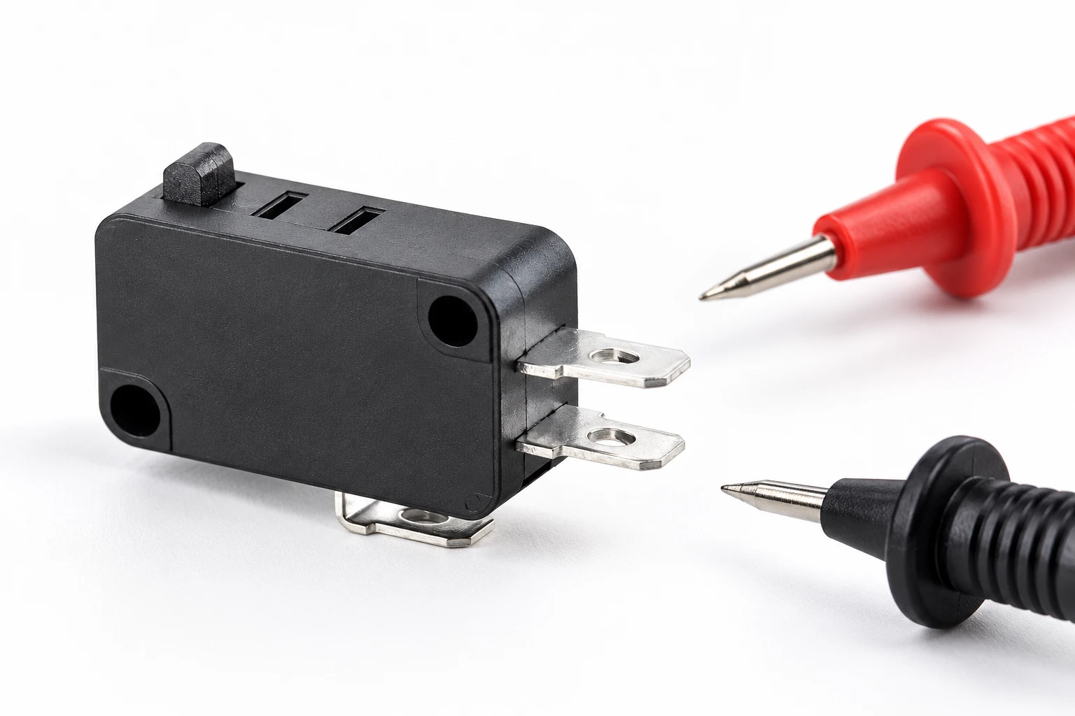
Separate three measurements before reviewing a datasheet
Closed-contact resistance concerns the intended conductive path through a contact pair. It matters when assessing connection loss, voltage drop and the condition of the mating contact surfaces. Insulation resistance concerns paths that are intended to remain insulating. These can include separated contacts or a terminal and an accessible conductive part, depending on the component construction and the applicable test specification. A good value for one path does not establish the performance of another.
Dielectric withstand testing applies a defined electrical stress and checks the specified acceptance conditions. Those conditions may include leakage limits and the absence of breakdown or flashover. The voltage, waveform, ramp, duration and current limit belong together. Removing these details from a comparison can make two unlike tests appear equivalent. The IEC catalogue identifies IEC 61058-1 as a general requirements standard for appliance switches. Its scope is a starting point for identifying the relevant component requirements; the catalogue description does not replace the full applicable test method.
| Propriedade | Path being assessed | Useful comparison information | What it cannot prove |
|---|---|---|---|
| Contact resistance | The intended closed conductive path | Contact state, measuring circuit and conditioning | Insulation between separated conductors |
| Insulation resistance | A specified insulating path | DC test voltage, time, environment and minimum resistance | Continuous current rating or contact life |
| Dielectric withstand | A specified insulation barrier under electrical stress | Waveform, voltage, duration, test path and acceptance limits | A continuous operating voltage equal to the test voltage |
This is a qualitative comparison of measurement purposes. The pass limits must come from the applicable component specification and equipment requirements, rather than from the table.
Read the insulation resistance entry as a complete condition
A resistance value without its conditions is incomplete. Identify whether the stated limit is an initial value, a value after environmental exposure, or an in-service maintenance criterion. Also identify the terminal combination, the actuator position and the environmental conditioning. A sample measured immediately after removal from damp storage may not be comparable with a dry sample prepared under a different laboratory procedure.
The current KW7 family page lists an initial insulation resistance minimum with a specified DC test voltage. Treat this as a family-page reference that needs confirmation against the ordered variant and approved drawing. It does not establish the same limit for every LEMA series, and it does not mean that an assembled controller should receive the component’s test voltage. Electronic inputs, indicator circuits and surge protection connected to the switch may require different handling.
Insulation measurements can also change while a test settles because current includes charging and material-related effects. Fluke’s explanation of insulation resistance measurement describes why timing and the nature of the insulating system affect interpretation. Do not transfer a motor-maintenance timing rule to a small switch without a relevant specification. Record the reading time that the component procedure actually requires.
Interpret the dielectric strength entry by test path
A switch can have different requirements between separated terminals and between terminals and non-current-carrying metal parts. These are different physical barriers. Before comparing suppliers, draw the proposed test paths on an approved component diagram. Identify which contacts are open in each actuator position, whether terminals must be grouped, and which metal features are included. Ask the supplier to resolve ambiguous wording instead of guessing from a photograph.
The KW7 page separates terminal-related and metal-part-related withstand entries. That distinction is more useful than extracting the largest voltage shown on the page. The wording on a general product page may be abbreviated or translated; the laboratory should use a controlled specification with an unambiguous terminal map. A generic mention of ground does not prove that a particular switch has a protective-earth terminal.
AC and DC withstand values should not be substituted using an informal conversion. The relevant test method, equipment classification and acceptance limits govern the comparison. Likewise, a shorter production test is not automatically interchangeable with a longer qualification test. If two quotations use different methods, request the method references and a written explanation before treating either number as superior.
Specify a safe, isolated laboratory review
High-voltage testing belongs in an appropriate controlled test area with qualified personnel, suitable instruments and an approved procedure. Define isolation from the machine and other circuits before planning the measurement. The UK Health and Safety Executive’s guidance on safety in electrical testing at work discusses controlled test areas, isolation arrangements and competent personnel. A component test still needs its own hazard assessment, discharge arrangements and access controls.
Start the request with the exact question: incoming conformity, design qualification, investigation after exposure, or validation of a substitute. These purposes can require different samples and acceptance decisions. Testing an unknown used component repeatedly at a withstand level may alter the evidence you are trying to investigate. Preserve failed samples, record their history and agree the sequence with the laboratory before conducting potentially stressful tests.
Document the instrument identity, calibration status, fixture and connections. A contaminated fixture or an unintended parallel path can dominate the reading. An assembled harness introduces additional insulation surfaces, connectors and cable jackets; results from that assembly cannot automatically be attributed to the switch alone. When possible, define separate component and assembly questions so that a failure can be traced to a meaningful boundary.

Control moisture, contamination and handling
An insulating surface can be affected by residues, conductive debris or moisture. A low reading does not immediately prove that the molded housing material is defective. Record whether the sample was exposed to cleaning chemicals, flux, machining dust or condensation, and whether it was measured as received or after an agreed conditioning step. Cleaning before documenting the initial condition can remove useful evidence.
Keep sample handling consistent. Touching a test surface, resting a terminal against a conductive tray or changing the cable arrangement can introduce an unwanted path. The solution is a defined fixture and handling procedure, rather than selecting the best reading from repeated attempts. If conditioning is permitted, retain both the initial result and the conditioned result with the associated method and elapsed time.
Environmental suitability remains a separate question. A favorable dry insulation measurement does not establish a water-ingress rating, suitability for condensation, or long-term resistance to a cleaning agent. Review the enclosure, cable entry and installation environment alongside the component specification. For wider component selection, see the guia de seleção de micro-interruptores industriais; verify the product documentation for each proposed condition.
Make a useful comparison and acceptance record
Prepare one row for each supplier and test path. Include the complete order code, drawing revision, contact form, actuator state, sample condition, test method and acceptance limit. Separate what the supplier states from what your laboratory actually measures. A quotation with a larger headline value but an unclear path should remain unresolved, rather than receiving a higher score by default.
For example, consider two candidate switches for an isolated control assembly. Supplier A provides a resistance limit but omits the test voltage. Supplier B provides a voltage and duration but describes only a terminal-to-frame test. Neither record yet answers a requirement about insulation across open contacts. The next action is to obtain the missing test definition, not to average the values or use continuity readings as a substitute.
Decide the disposition before testing. An incoming inspection might accept a documented lot, quarantine it, or send samples for investigation. A substitution review may require additional equipment-level verification even when the individual component meets its specification. Keep the decision tied to the relevant requirement and preserve traceability between the sample, report and received lot.
What to send with a LEMA technical inquiry
Provide the intended circuit function, normal operating conditions, complete candidate code and the insulation paths you need assessed. Include the equipment requirement or test-method reference, any environmental conditioning, and whether the question concerns a bare switch or a finished harness. Ask for the applicable drawing and variant-specific test conditions, rather than requesting a generic certificate without identifying its scope.
If the real concern is loss through closed contacts, use the separate micro switch contact resistance guide. For a basic isolated contact-state check, see testing a micro switch with a multimeter. These complementary checks answer different questions and should appear separately in an inspection plan. Contact LEMA with the application and documentation request before approving a substitution.
Further learning: why dielectric materials behave differently
The following NPTEL lecture, Dielectric (Insulating) Solids, provides university-level background on dielectric materials. It helps explain the physical basis of insulation, rather than prescribing a micro switch acceptance test. Use the component specification and qualified laboratory procedure for the actual test conditions.

Watch the NPTEL lecture on YouTube.
Perguntas frequentes
Is insulation resistance the same as contact resistance?
No. Contact resistance concerns an intended closed conductive path; insulation resistance concerns a specified path that should remain insulating.
Can a multimeter continuity test prove dielectric strength?
No. Continuity checking does not apply the specified withstand stress or evaluate the required insulation barrier under its defined test conditions.
Can a withstand test voltage be used as the operating voltage?
No. A specified test stress and duration do not establish the permitted continuous operating voltage of a switch or the finished equipment.
What should I do when a supplier’s test-path description is unclear?
Request a controlled test specification and terminal diagram for the complete order code, and resolve the ambiguity before comparing results or authorizing a laboratory test.