
An illuminated toggle adds a second communication circuit to the panel. Decide what the indicator means, where it is sourced, and how service verifies it before the design team releases the harness.
Important: an illuminated appearance does not establish a lamp or LED voltage, current rating, ingress result, approval or life. Confirm every model-specific limit in the selected documentation. Source note: IEC 61058-1 publication scope and selected-model documentation.
– FAQ
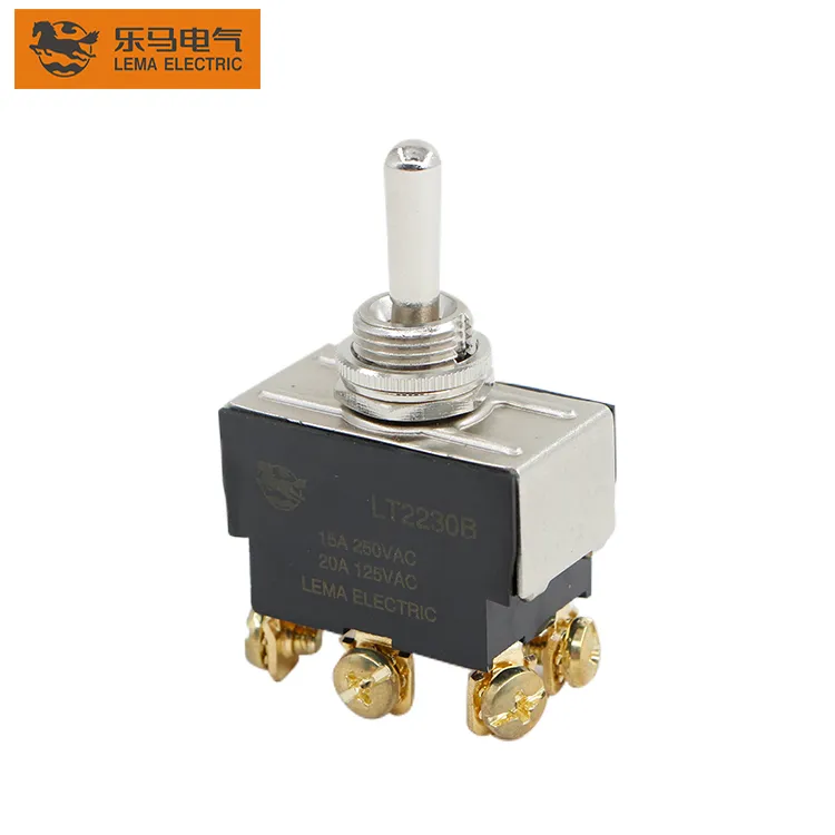
Part 1. What does illumination add to a toggle circuit?
The indicator communicates a chosen condition to an operator; the switch contacts control a circuit. Those conditions may align, but they must never be assumed to be identical. Capture whether the legend should show source availability, a selected state, an active load, or a fault-related condition, then build the drawing around that decision.
| Decision field | Record in the package | Send with quote |
|---|---|---|
| Meaning | What the panel indication represents | Yes |
| Source | Where the indicator circuit is fed | Yes |
| State | Which circuit state is intended to be visible | Yes |
| Service | Legend, test point and replacement path | Yes |
Begin product-family navigation at the LEMA Toggle Switch product line after those inputs are written.
Part 2. Which source and state inputs belong on the drawing?
Show the main load path and the indicator path separately. A source-powered indicator can communicate panel availability while a load-following indicator can communicate a switched condition; the intended user meaning must be stated rather than guessed from the front legend. Include the expected supply class, circuit form and maintenance state in the drawing package.
The ON-OFF versus ON-OFF-ON guide is useful when the lever positions themselves need a separate state-logic review.
Part 3. How should indicator terminals and harness routing be controlled?
Mark indicator leads and contact terminals distinctly, and keep them on the same controlled schematic revision. Route the harness so an operator or service technician cannot mistake an indicator lead for a load conductor. Any connector, terminal treatment or strain-relief decision belongs in the released assembly instruction.
For common and throw identification, use the SPDT terminal-identification guide instead of relying on a generic three-terminal assumption.
Part 4. How do panel legends and service visibility affect the design?
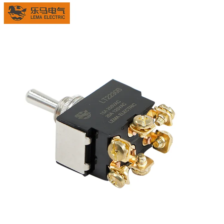
A visible lens is useful only if the legend tells the truth. Review viewing angle, label location, daylight or low-light context, service access, and what happens when the panel supply is absent. Build a test sequence that compares lever state, indicated state and actual circuit state before labeling the design complete.
- Use a controlled legend that states the intended condition.
- Keep service access separate from lever operation space.
- Document which test proves the indicator path.
- Use the 12V OEM panel guide only as low-voltage context, not as a model wiring claim.
Part 5. Why must the indicator remain separate from load assumptions?
An indicator can be working while the controlled load is not, or the load can be present while a separate indicator source is unavailable. The design review must identify that boundary so an operator does not treat a lamp as proof of an electrical result. Keep load, inrush, terminal process and selected-model documentation in the main circuit review.
Part 6. What should be validated before sample approval?
On a production-intent panel, test each specified lever state, verify the intended indicator behavior, isolate the source and load paths as required, and confirm a technician can follow the service drawing. Preserve the selected documentation with the sample record.
Fit Boundary: this guide structures indicator-circuit and panel-communication planning. It does not certify illumination voltage, rating, ingress, approval or life for any model.
Part 7. How can LEMA support an illuminated-toggle inquiry?
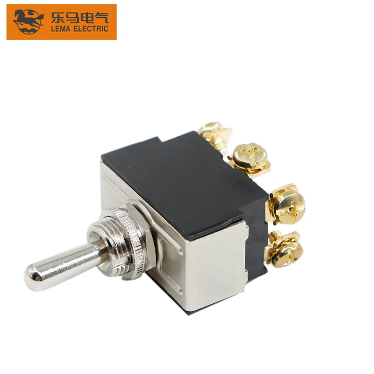
Use the LT1 series toggle switch page as a public starting point once the indicator and main-circuit drawings are ready.
Send with the inquiry:
- Legend meaning and required visible state
- Source and main-load schematic
- Terminal, harness and panel-access notes
- Environment, volume, sample timing and requested documentation
Send a toggle-switch RFQ with the controlled circuit package.
## FAQ
What should an illuminated toggle drawing show?
Show the main load circuit, indicator circuit, intended visible state, terminal labels, legend and service test.
Does the indicator always follow the switched load?
No. The source and intended meaning must be stated on the drawing rather than inferred from the front appearance.
Can an indicator lead be treated as the main load lead?
No. Keep indicator and main-circuit assignments distinct in the schematic and harness plan.
How should panel legends be checked?
Test each lever and circuit state on a representative panel, then confirm the legend communicates the documented condition.
What documentation is needed before sample approval?
Use the controlled schematic, terminal map, panel drawing, test sequence and selected-model documentation.
What belongs in an illuminated-toggle RFQ?
Include the required indication meaning, source and state logic, circuit form, terminals, panel context, volume and sample timing.
## References