
Push button switch troubleshooting works best when you separate four possible faults: the actuator, the electrical contacts, the wiring, and the receiving control circuit. A button that feels normal can still have a bad connection; a working contact can still send a signal that the machine ignores. Begin with the circuit drawing and the expected released and pressed states, then isolate the machine before inspecting or measuring the switch. This guide helps industrial equipment builders and maintenance teams locate the fault without assuming that every failure requires a new button.
The examples concern ordinary control inputs. Emergency stops, guard circuits and other protective functions require their own approved procedures and validation. Never bypass a protective device to keep production running.
Record the symptom before moving any wires
Write down exactly what fails: no response, delayed response, several responses from one press, a button that stays down, or an indicator lamp that stops working. Also record whether the failure occurs after cleaning, after vibration, at startup, or only after the equipment has been running. These conditions help distinguish a damaged component from installation stress or a problem elsewhere in the circuit.
Identify the switch order code, drawing revision, terminal designations, control voltage, connected load and intended action. A maintained button should remain in its selected state; a momentary button should return when released. Mistaking one for the other produces a false diagnosis. Compare the installed device with the approved bill of materials rather than relying on color or appearance.
Use the industrial push button selection guide to review the original application requirements. Troubleshooting should confirm those requirements, not quietly change them.
Isolate energy before mechanical or continuity checks
Stop the equipment through its approved process. Isolate the relevant electrical supply and address stored or non-electrical energy under the site’s procedure. A stop command or an open control contact is not an energy isolator. OSHA’s hazardous-energy guidance explains why servicing requires a controlled isolation process where unexpected startup or stored energy could injure workers.
Continuity and resistance measurements belong on a de-energized circuit with the switch sufficiently disconnected to remove misleading parallel paths. Qualified personnel should verify the safe condition and follow the meter manual. Do not change the meter to resistance mode while it remains connected to an energized circuit. Keep any powered diagnostic work separate, authorized and based on the actual installation.
Photograph the original connections before disconnecting conductors. Mark each wire with its drawing reference. Keep terminal identification and connector orientation in the record so a correct diagnosis does not become an incorrect reassembly.
Use the symptom to choose the next check
| Observed symptom | First isolated check | Evidence to record | Next decision |
|---|---|---|---|
| Button will not return | Inspect cap clearance, collar seating and visible contamination | Whether the actuator returns freely outside the stressed installation | Correct mounting or replace a damaged assembly; do not add unapproved lubricant |
| Normal movement but no response | Check the intended contact pair in both actuator states | Released and pressed readings against the terminal diagram | Separate a contact fault from wiring or controller problems |
| Works only when cable moves | Inspect connectors, strain relief and conductor damage | Fault location and the effect of gentle movement under safe isolated conditions | Repair the approved harness connection rather than repeatedly replacing buttons |
| Indicator dark but command works | Identify the separate lamp circuit and its rating | Lamp supply, polarity where applicable and connection identification | Investigate indication separately from the switching contact |
| Repeated commands from one press | Compare contact state with input diagnostics and program behavior | Whether the symptom begins at the physical contact or downstream | Review bounce, input filtering and application logic without masking a damaged contact |
| Heat, odor or discoloration | Remove the assembly from service and inspect the load and connection | Damage, terminal condition and actual duty requirements | Find the cause before installing a replacement |
This is a qualitative diagnostic sequence, not a set of universal electrical acceptance limits. Use the switch, connector and controller documentation for the installed models.
Check the actuator and mounting as an assembly
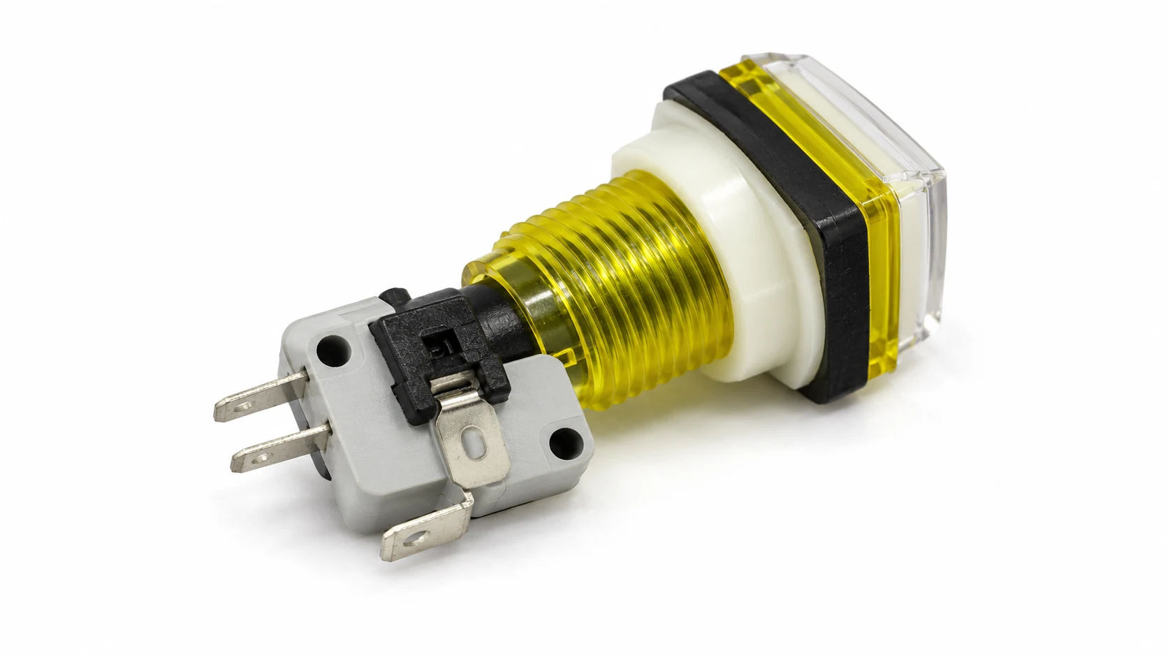
Look for a crooked collar, a cap rubbing against the panel, a cracked housing, displaced seal or a mounting opening that does not match the drawing. A switch may work on a bench but bind after installation because the panel compresses or misaligns part of the assembly. Check the clearance behind the panel too: a wire bundle or adjacent component can prevent full travel.
Operate the isolated actuator slowly through its normal travel. It should follow the specified action without forcing it beyond the intended stop. Record any difference between straight and angled pressing. A defect that appears only under side pressure may indicate alignment or operator-access problems. Do not use additional force as a remedy, and do not file a cap or alter the mechanism unless the manufacturer explicitly permits that repair.
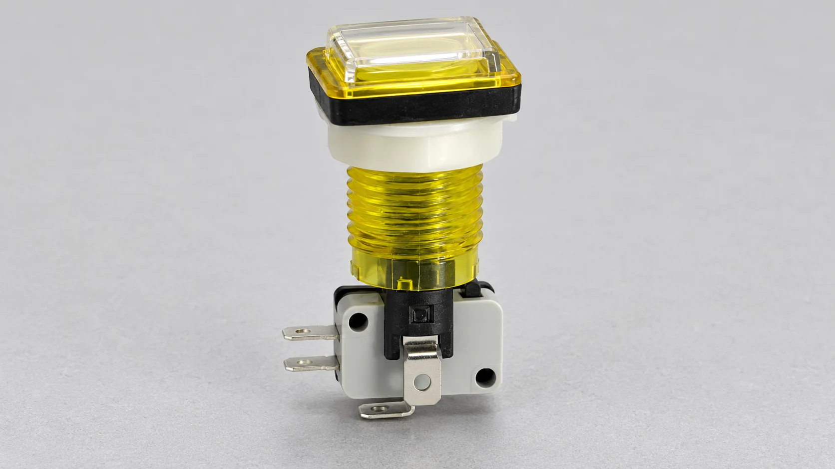
The LEMA PBS product family provides real product examples for checking physical form and mounting requirements. The illustrations in this article show one reference configuration; they do not establish the ratings or terminal functions of every PBS variant.
Verify the contact pair independently of the machine
Read the exact terminal diagram. Terminal position, a molded number or the number of pins alone is not enough to identify the complete circuit. A device may contain a changeover contact, separate contacts or an independent illumination circuit. Use the drawing to identify the intended normally open or normally closed pair.
Check the meter leads first by following the instrument’s instructions. Then measure the identified isolated contact in the released state and in the fully operated state. Record both readings rather than writing only “beeps.” A continuity sound is a screening indication whose threshold depends on the meter. It is not proof that the contact will perform correctly under the application’s actual electrical duty.
Repeat several normal operations and watch for readings that fail to settle or change unpredictably. Keep the probes secure so movement at the test connection does not imitate an intermittent switch. A simple hand-operated check cannot establish electrical endurance, insulation performance or compliance with a machine safety function.
For contact-state background, see normally open versus normally closed push buttons. If the isolated switch changes state correctly, reconnect it only through the approved procedure and continue tracing the signal path.
Separate wiring faults from controller interpretation
A healthy switch cannot compensate for an open conductor, loose connector, wrong reference connection or incompatible input circuit. Inspect the actual path from the switch terminals to the receiving input. Include intermediate connectors and terminal blocks, and compare each connection with the current drawing. Look for conductors pulled tight by the panel door, unsupported cable weight and evidence of moisture or cleaning-fluid entry.
Where the assembly uses a separate contact block, confirm that it is mechanically seated and is the correct compatible part. Similar-looking blocks can have different functions. The contact block guide explains the selection questions; a troubleshooting replacement must still match the approved assembly.
For a PLC input, compare the field condition, module indication and program status through an authorized diagnostic process. A change on the module does not guarantee that the application will execute the requested action: another permissive, operating mode or interlock may prevent it. Conversely, the symbol used in a program does not necessarily describe the physical contact’s resting state. Read the signal assignment before blaming the button.
Use a related video to understand the input signal path
RealPars’ teaching video below illustrates troubleshooting a PLC digital input associated with a push button. It supports the distinction between the field device, wiring and receiving module. Its example hardware and powered measurements are not a substitute for your site’s procedure or the specifications of the installed equipment.
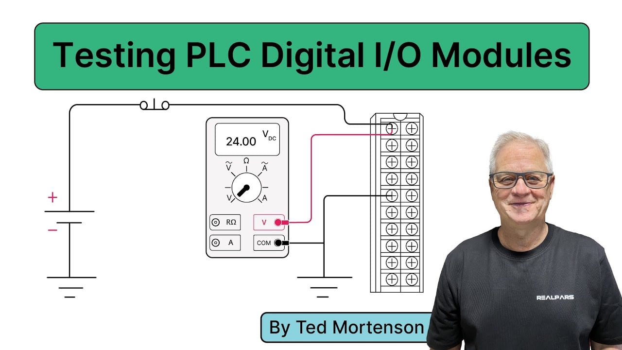
Learning source: RealPars digital I/O troubleshooting lesson. Open the video on YouTube.
Treat illumination and repeated signals as separate evidence
An illuminated cap may be wired to show supply availability, a command or confirmed machine status. Those meanings are different. If the lamp is dark but the contact operates, first determine which circuit drives the lamp. Check its specified voltage and connection arrangement; polarity matters only where the particular lamp assembly requires it. Do not assume a lamp terminal is a switching terminal.
When one press produces repeated commands, establish where the repetition begins. A failing connection, normal contact bounce, an unsuitable input configuration or a program that repeatedly responds to a held signal can create different remedies. Compare the physical signal with the application behavior before adding a delay. Extra filtering can hide symptoms or alter response time, which matters for some control functions.
Review contact bounce and input handling for the shared electrical principle. This article focuses on finding the faulty layer rather than designing a new debounce circuit.
Repair the cause and validate the assembled control
Replace damaged sealed components through an approved part substitution process. Do not open a sealed contact assembly, polish internal contacts or use a cleaner that lacks compatibility approval. A replacement chosen only by panel fit may change contact behavior, environmental protection or electrical duty. Investigate excess load, vibration, misalignment and chemical exposure so the new part does not fail in the same way.
After restoring the original wiring and removing temporary test equipment, complete the authorized return-to-service process. Verify the released and operated states, indication, machine response and all functions affected by the work. Observe the equipment under representative permitted operating conditions. Record the fault cause, corrective action, replacement order code and validation results.
For an OEM inquiry, provide photographs, the switch drawing, terminal diagram, control-circuit duty, panel dimensions, environment and the failure record. These details help LEMA assess a suitable component without guessing at compatibility or claiming that an ordinary button qualifies an entire machine.
Frequently asked questions
Why does the button click but the machine does nothing?
A click confirms mechanical movement, not the complete electrical signal path. Check the isolated contact, wiring and controller conditions separately.
Does a continuity beep prove the switch is good?
No. It is a preliminary check of a conductive path. It does not prove performance under load, endurance, insulation or a safety function.
Should I replace a button when its lamp fails?
Identify the illumination circuit first. A lamp supply or wiring fault can occur while the switching contact remains functional.
Can I bypass the switch while troubleshooting?
Do not bypass protective functions or leave a temporary connection in service. Any diagnostic simulation must follow an authorized machine-specific procedure.